Optical sensor assembly for installation on a current carrying cable

a technology of optical sensor and current carrying cable, which is applied in the direction of instruments, fault locations, measurement devices, etc., can solve the problems of increasing complexity and cost, and requiring a large amount of installation tim

Active Publication Date: 2013-02-07
MICATU
View PDF2 Cites 8 Cited by
  • Summary
  • Abstract
  • Description
  • Claims
  • Application Information

AI Technical Summary

Benefits of technology

[0017]An objective is to provide an optical sensor assembly for installatio...

Problems solved by technology

Hence they are expensive and cumbersome to install.
It is, however, difficult to make use of the current sensor disclosed.
This adds to the complexity and the cost.
However, the prior art does not teach an economica...

Method used


Image

  • Optical sensor assembly for installation on a current carrying cable
  • Optical sensor assembly for installation on a current carrying cable
  • Optical sensor assembly for installation on a current carrying cable

Examples


Embodiment Construction

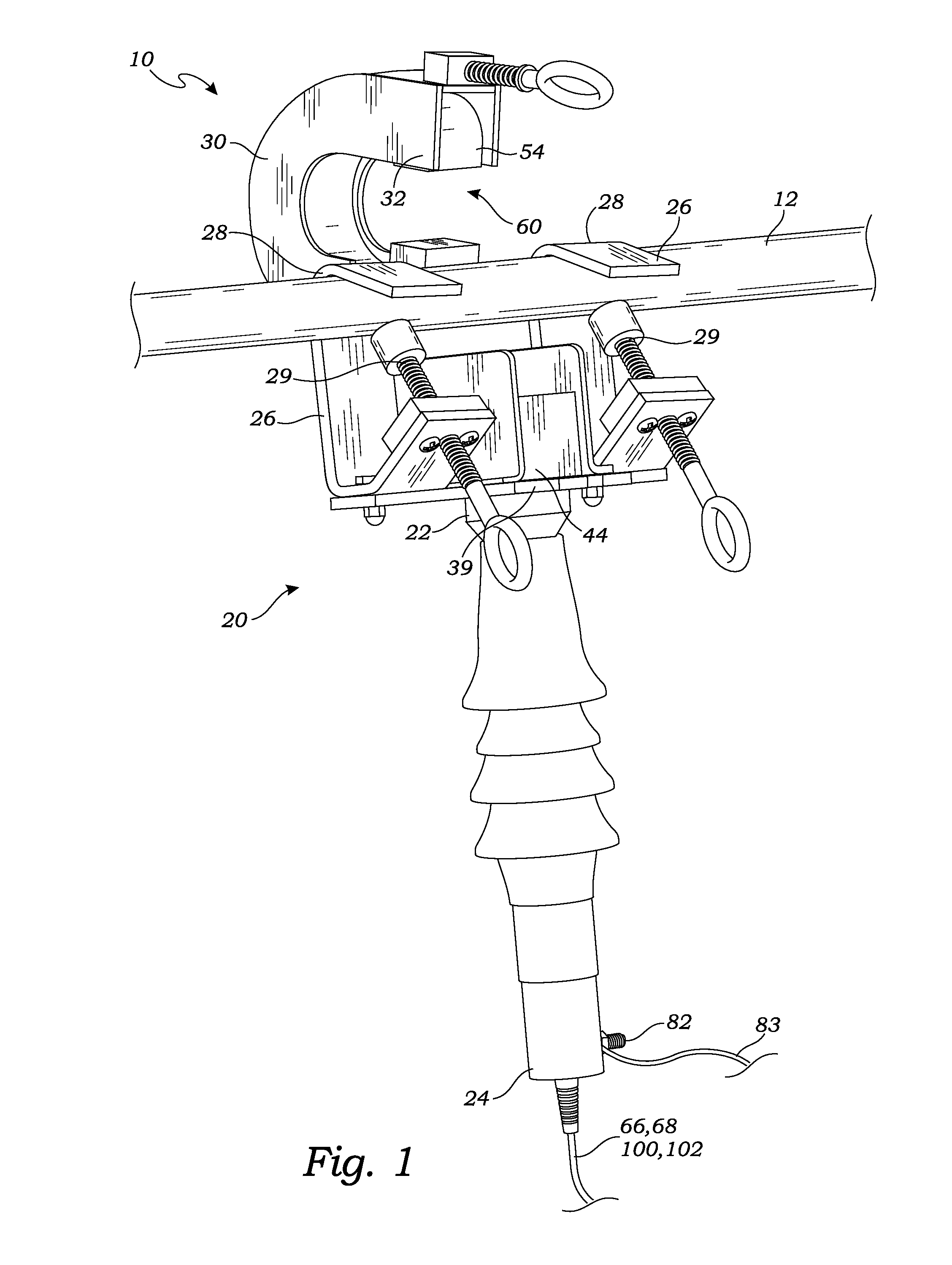
[0042]FIG. 1 is a perspective view of one embodiment of the optical sensor assembly 10 wherein the magnetic concentrator 54 is in the open position and has not yet been placed in a position to encompass or partially encompass the current carrying cable. It is noted, nevertheless, that in this position, the current carrying cable 12 is firmly held by the optical sensor assembly 10.

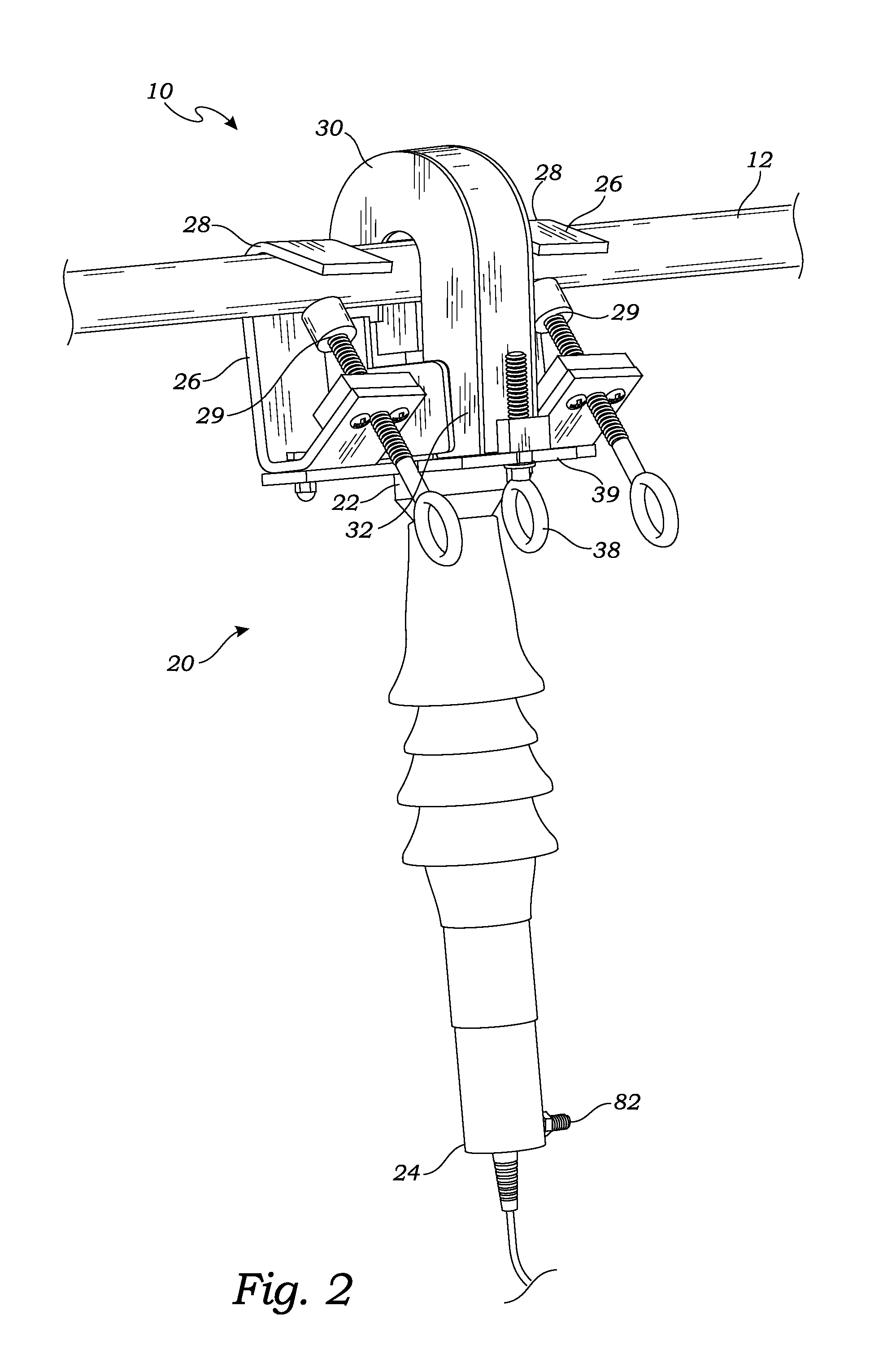
[0043]FIG. 2 is a perspective front view of FIG. 1, showing the magnetic concentrator in closed position showing housing 30 locked in place by locking element 38. Referring to FIGS. 1 and 2, the base unit 20, which extends from hooks 26 to the bottom of the optical sensor assembly 10, uses two hooks 26, as shown, for hanging the base unit 20 from the current carrying cable 12. Only one hook, by itself, or, possibly, with additional ties, strapping or other structure may be used. In the embodiment of FIG. 1, a pair of hooks 26, one on either side of a light directing device 44, (which in one embodiment, is s...


PUM


Abstract

An optical sensor assembly, for installation on a current carrying cable, senses the current in the cable and provides an electrical output indicating the current. To sense the current, a magnetic concentrator is placed in close proximity to the cable and creates a magnetic field representing current in the cable. An optical current sensor, within the created magnetic field, exposes a beam of polarized light to the magnetic field. The beam of polarized light is rotated thereby, by Faraday effect, according to the current in the cable. The amount of rotation is analyzed and converted to electrical signals to portray the current in the cable. The electrical signals may be processed, evaluated and analyzed to provide one or more of several elements of quality of the current in the cable.

Description

CROSS-REFERENCE TO RELATED APPLICATIONS[0001]This application is a Continuation-in-Part of patent application Ser. No. 12 / 612,894, filed Nov. 5, 2009 and still pending, which is a continuation-in-part of a previously-filed patent application, application Ser. No. 12 / 607,954, filed Oct. 28, 2009, which issued Dec. 13, 2011, as patent No. 8,076,925. This application hereby incorporates by reference, the teachings of both said cases.STATEMENT REGARDING FEDERALLY SPONSORED RESEARCH[0002]Not ApplicableBACKGROUND OF THE INVENTION[0003]1. Field of the Invention[0004]This invention relates to an optical sensor assembly for installation on an electrical current carrying cable and sensing much information about the current in the cable, and, further, embodiments of an optical sensor assembly combined with an electronics systems, (preferably, located a distance away from the cable), and capable of one or more of sensing, measuring, indicating, analyzing and evaluating the current in the cable....

Claims


Application Information

Patent Timeline
IPC IPC(8): G01R19/00G01R31/08
CPCG01R1/071G01R15/247G01R15/246G01R15/142G01R19/0092
Inventor HARLEV, JOSEPH YOSSIJOHNSON, LEONARDVEAZEY, RHADKONETSKI, THEODORE
Owner MICATU
Why Eureka
Try Eureka