

Diaphragm pump
a diaphragm pump and pump body technology, applied in the direction of pump, positive displacement liquid engine, liquid fuel engine, etc., can solve the problems of difficult automatic mounting work and inability to reduce the number of parts, and achieve the effect of reducing the number of parts
- Summary
- Abstract
- Description
- Claims
- Application Information
AI Technical Summary
Benefits of technology
Problems solved by technology
Method used
Image

Examples
first embodiment
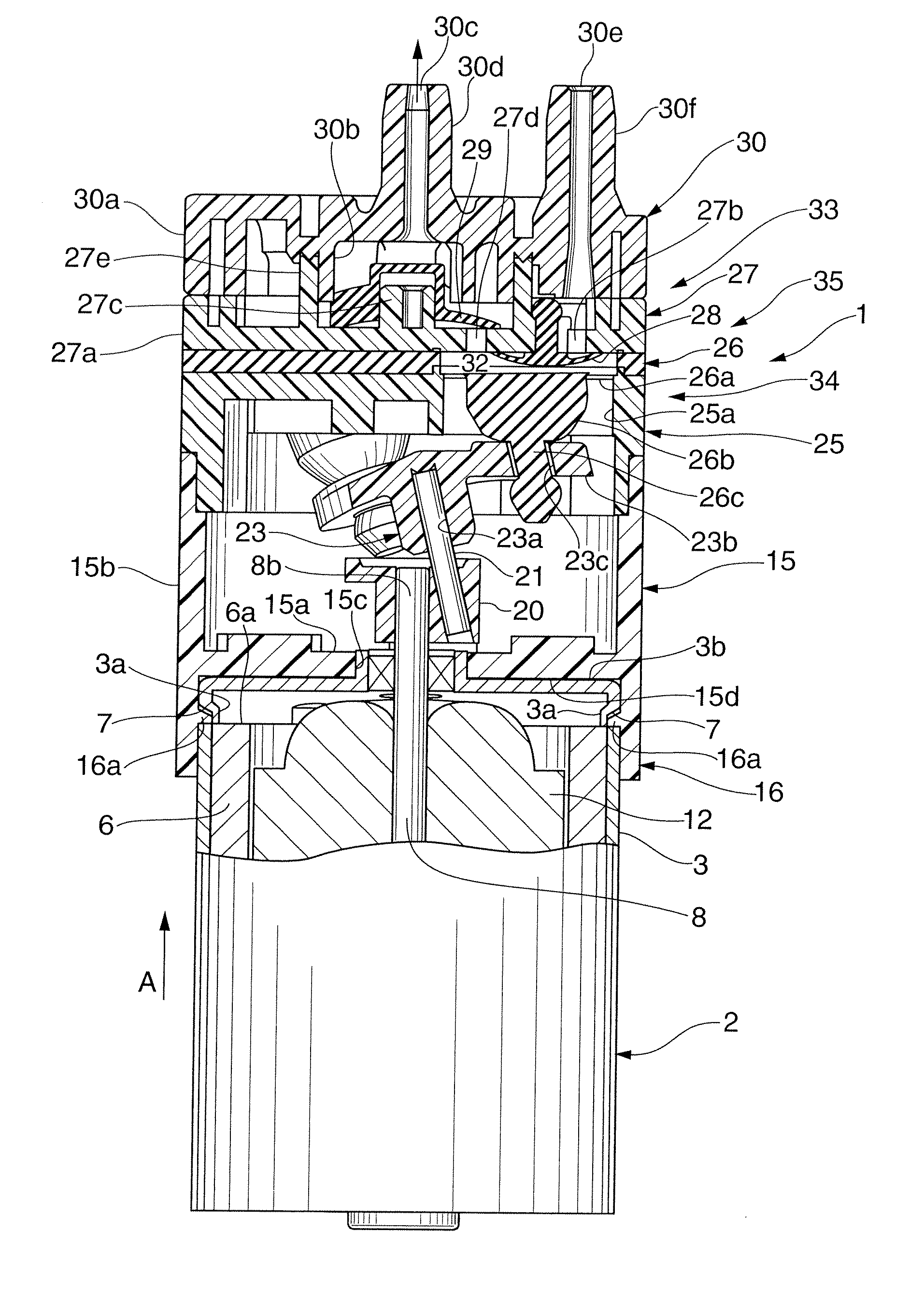
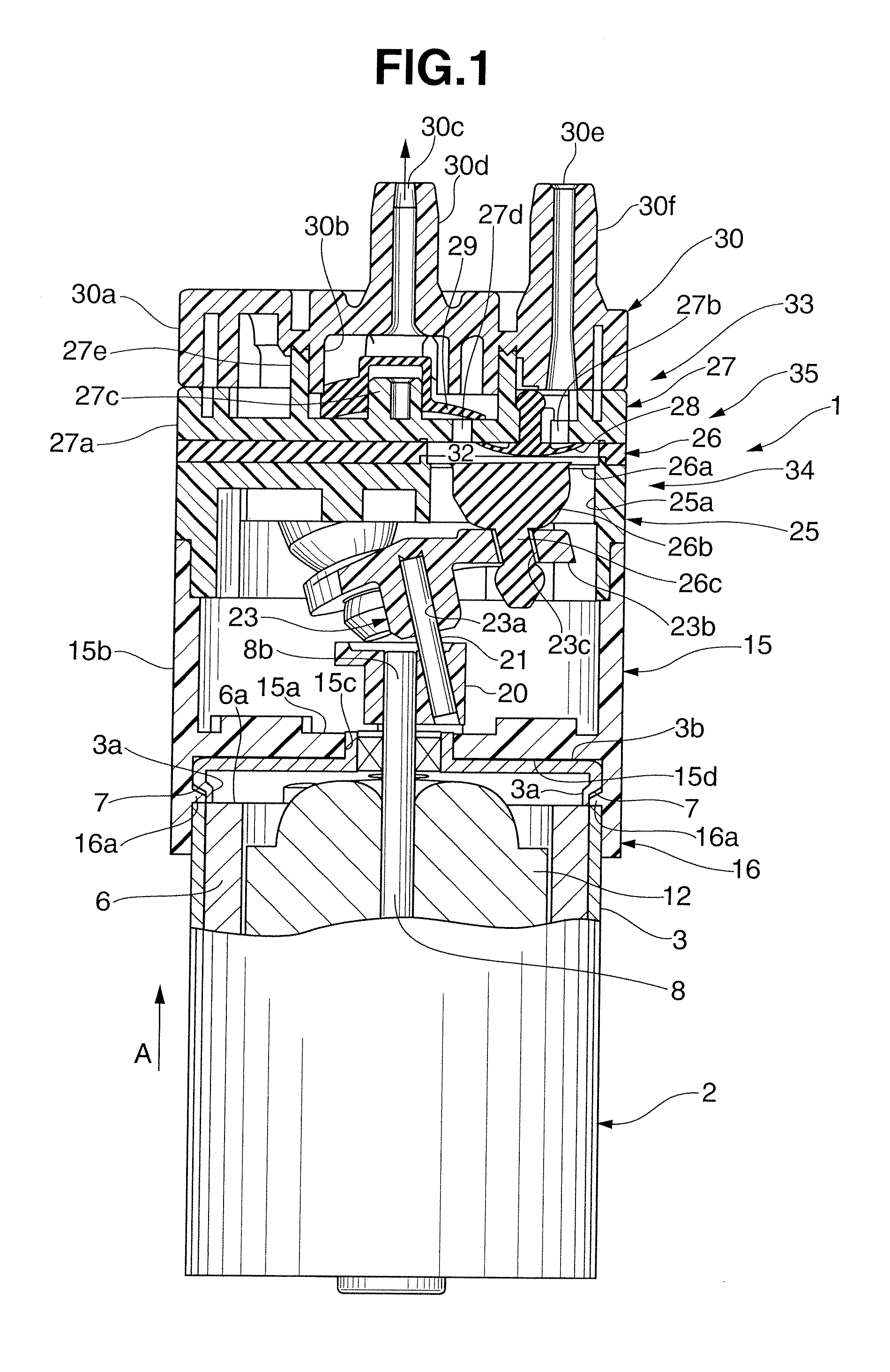
[0019]First, the first embodiment of the present invention will be explained with reference to FIGS. 1 to 3B. As shown in FIG. 1, a diaphragm pump 1 according to this embodiment includes a motor 2 as a driving source having a circular planar shape. As shown in FIG. 2, the motor 2 includes a motor housing 5 including a cap-like yoke 3 having an open lower end and a bottom plate 4 for closing the opening of the yoke 3. A plurality of recesses 7 are formed in the circumferential direction in the outer circumferential surface of the upper portion of the cylinder of the yoke 3, at the same time an abutting portion 3a is formed toward the inside of the yoke 3 by indenting. The plurality of recesses 7 are formed in the same position in the direction of an arrow A (in the direction of the height in the drawings). A permanent magnet 6 is attached to the inner circumferential surface of the yoke 3. The permanent magnetic 6 is pressed in the yoke 3 from below, and attached to a predetermined p...
second embodiment
[0047]The second embodiment of the present invention will be explained below with reference to FIG. 4. The second embodiment differs from the above-described first embodiment in that a mounter 15 has no bottom portion 15a and has a cylindrical shape having open upper and lower ends. When mounting a motor 2 on the mounter 15 in this arrangement, the motor 2 is fitted in the mounter 15 from below in the same manner as in the first embodiment.
[0048]Then, the motor 2 is pressed in as it is moved in the direction of an arrow A. Consequently, recesses 7 of the motor 2 engage with projections 16a of the mounter 15 while the mounter 15 elastically deforms, thereby mounting the motor 2 on the mounter 15. In the second embodiment, as in the first embodiment described above, no screws are necessary to mount the motor 2 on the mounter 15, and the motor 2 can be mounted on the mounter 15 by only almost linearly moving the motor 2 in the direction of the arrow A. This facilitates introducing auto...
third embodiment
[0049]The third embodiment of the present invention will be explained below with reference to FIGS. 5 to 7. Note that an explanation of the same portions as in the first embodiment will be omitted.
[0050]In FIG. 5, reference numeral 115 denotes a crank formed into an almost columnar shape. A driving end portion 108b of an output shaft 108 of a motor 102 is fixed to the central portion of the crank 115, so the crank 115 rotates together with the output shaft 108. A driving shaft 116 has a lower end portion attached in an inclined state to a portion off-centered from the portion of the crank 115 to which the driving end portion 108b is attached.
[0051]Reference numeral 117 denotes a driving member having a non-through hole 117a in the center. Three driving elements 117b (two driving elements 117b are not shown) projecting in a direction perpendicular to the non-through hole 117a are formed integrally with the upper end portion of the driving member 117 at an equal angle (120°) in the ci...
PUM
 Abstract
Description
Claims
Application Information