
Surgical devices and methods providing sacroiliac stabilization

a technology of sacroiliac stabilization and surgical devices, applied in the field of surgical procedures, can solve the problems of high pelvic incidence or high risk of lumbo-sacral hardware failure, iliac fixation, and orthopedic traumatologists, and achieve the effect of improving the methods and devices for stabilizing the spine and/or the pelvis

Active Publication Date: 2013-02-07
DATTA DEVIN
View PDF10 Cites 60 Cited by
  • Summary
  • Abstract
  • Description
  • Claims
  • Application Information

AI Technical Summary

Benefits of technology

The invention provides better ways to stabilize the spine and pelvis. A new method involves inserting a base into the ilium with a channel. A support member is then inserted through the channel and secured to the base. This helps reduce surgery time and discomfort for patients.

Problems solved by technology

In addition, complex spine surgeries, such as for correction of sagittal plane deformity, often require iliac fixation to maintain correction in patients with a high pelvic incidence or high risk of lumbo-sacral hardware failure.
High energy pelvic ring injuries that involve disruption of the SI joint and / or displaced fractures of the sacrum present unique challenges to the orthopedic traumatologist.
Some sacral fractures require solid posterior stabilization, which may be difficult to achieve with typical treatment methods.
Furthermore, vertically unstable sacral fractures / SI joint disruptions have a relatively high incidence of neurovascular injury and may require unique stabilization.
However, there may be significant soft tissue trauma associated with these injuries, making extensive surgical approaches of elevated risk in terms of infection and wound complications.
Current techniques and instrumentation systems may require extensive surgical exposure and dissection.
Moreover, such instrumentation systems are typically designed for other applications, and not to connect and stabilize the lumbar spine and pelvis.
As a result, this can make the surgical times longer and more frustrating for surgeons and surgical staff.
Yet, this sometimes makes hardware painful for the patient and at risk for pressure soreness following surgery.

Method used


Image

  • Surgical devices and methods providing sacroiliac stabilization
  • Surgical devices and methods providing sacroiliac stabilization
  • Surgical devices and methods providing sacroiliac stabilization

Examples


Embodiment Construction

[0029]The present invention will now be described more fully hereinafter with reference to the accompanying drawings, in which preferred embodiments of the invention are shown. This invention may, however, be embodied in many different forms and should not be construed as limited to the embodiments set forth herein. Rather, these embodiments are provided so that this disclosure will be thorough and complete, and will fully convey the scope of the invention to those skilled in the art. Like numbers refer to like elements throughout, and prime notation is used to indicate similar elements or steps in different embodiments.

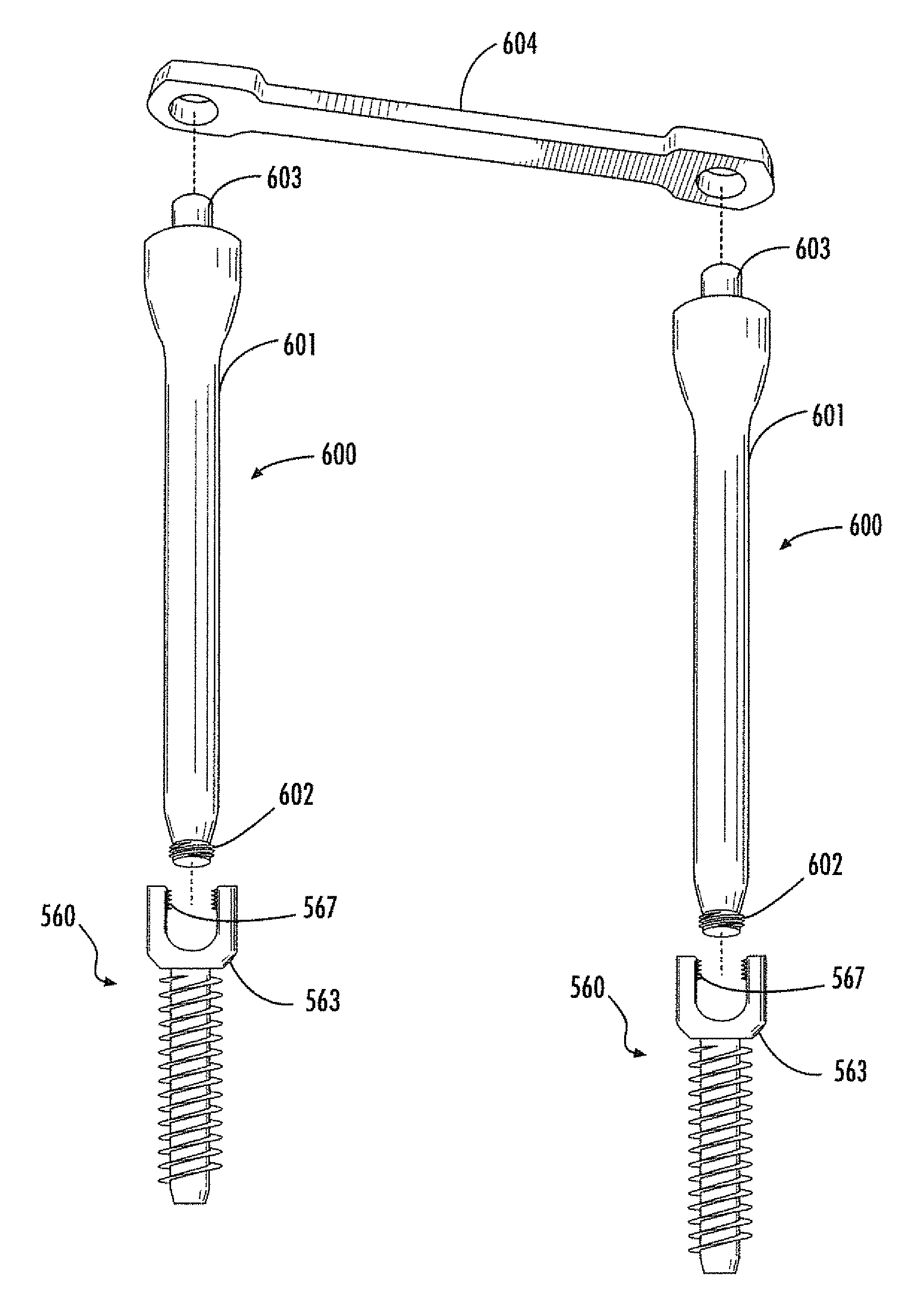
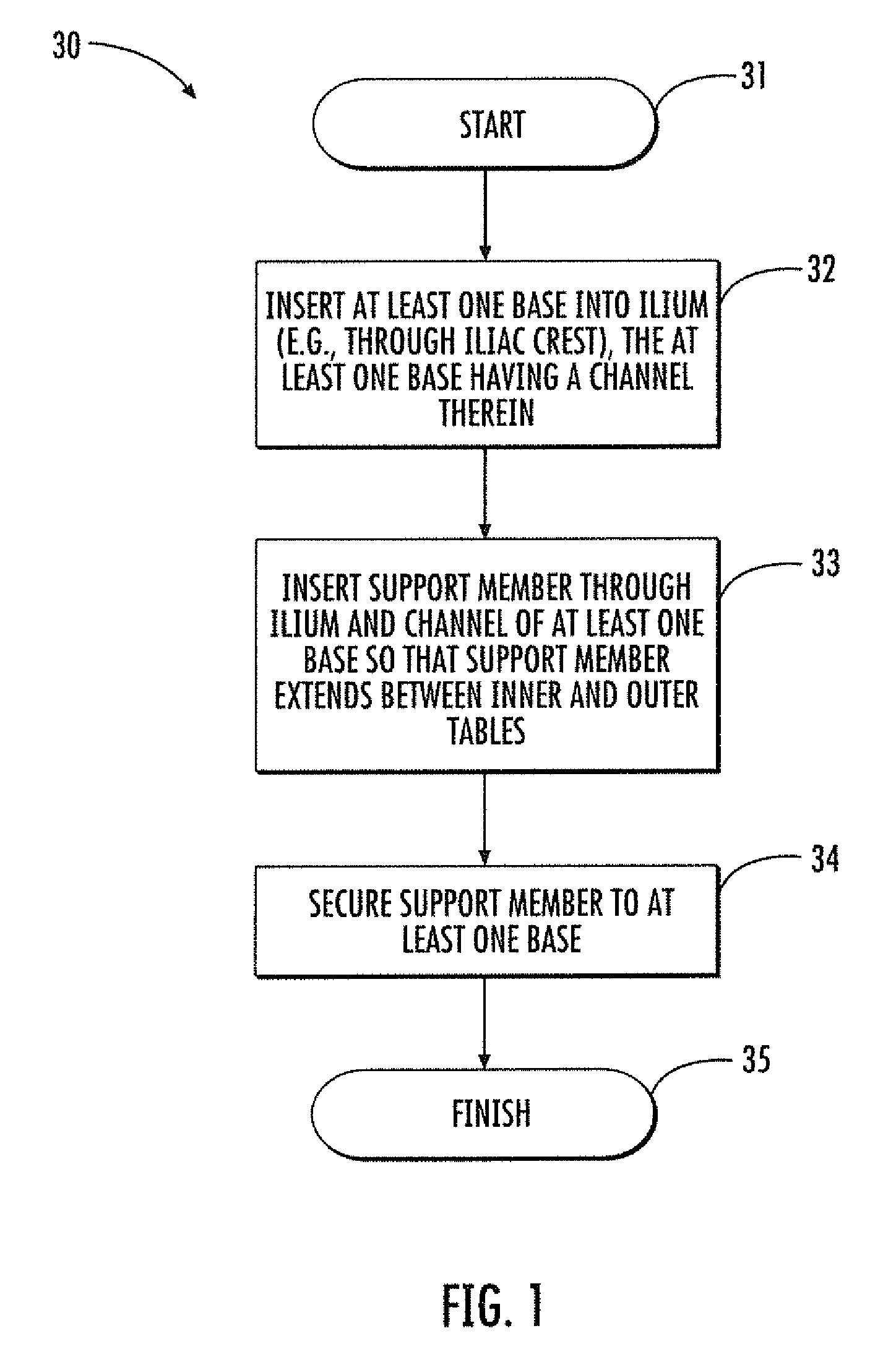
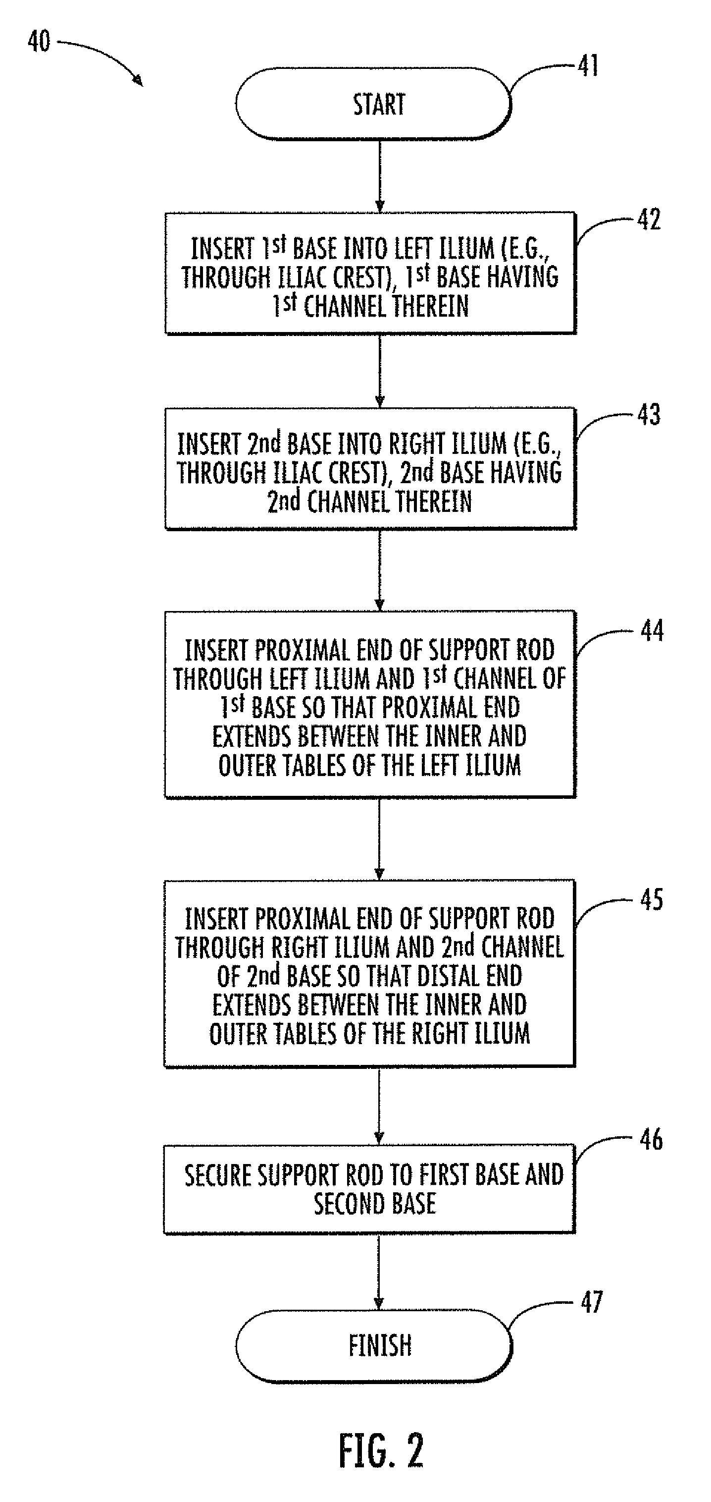
[0030]Referring initially to the flow diagram 30 of FIG. 1 and FIGS. 4 and 14, a surgical method and associated devices which may advantageously be used to provide stability to portions of a patient's lower back, including the lumbar spine 100, sacrum 101, and / or ilia (e.g., a left ilium 102 and a right ilium 103), are first described. Each ilium 102, 103 has a respe...


PUM


Abstract

A surgical method is for at least one ilium having an iliac crest and inner and outer tables on opposing sides of the iliac crest. The method may include inserting at least one base into the ilium, where the at least one base has a channel therein. The method may further include inserting a support member through the ilium and through the channel of the at least one base so that the support member extends between the inner and outer tables, and securing the support member to the at least one base.

Description

CROSS-REFERENCE TO RELATED APPLICATIONS[0001]The present application claims the benefit of U.S. provisional app. No. 61 / 515,075, filed Aug. 4, 2011, which is hereby incorporated herein in its entirety by reference.FIELD OF THE INVENTION[0002]The present invention relates to the field of surgical procedures, and, more particularly, to musculoskeletal surgical procedures and associated devices.BACKGROUND OF THE INVENTION[0003]The sacroiliac joint (SI joint) is increasingly being diagnosed as a common pain generator. That is, SI joint degenerative disease and instability are being diagnosed and treated more commonly. Contributing factors include post traumatic injury, accelerated wear / instability after lumbar fusion, post pregnancy pain / instability and longer life span combined with a more active lifestyle in many patients. In addition, complex spine surgeries, such as for correction of sagittal plane deformity, often require iliac fixation to maintain correction in patients with a hig...

Claims


Application Information

Patent Timeline
IPC IPC(8): A61B17/88A61B17/86
CPCA61B17/7032A61B17/864A61B17/8605A61B2017/1602A61B17/1757A61B17/7055A61B17/1631A61B17/1671A61B17/7049
Inventor DATTA, DEVIN
Owner DATTA DEVIN
Learn More