Split ply tires and bead area monocomponents

Inactive Publication Date: 2013-02-14
THE GOODYEAR TIRE & RUBBER CO
View PDF10 Cites 8 Cited by
  • Summary
  • Abstract
  • Description
  • Claims
  • Application Information

AI Technical Summary

Benefits of technology

[0030]“Pneumatic tire” means a laminated mechanical device of generally toroidal shape (usually an open-torus) having bead cores and a tread and made of rubber, chemicals, fabri

Problems solved by technology

Unfortunately, such a tire when made with a single carcass ply is difficult to mass produce because the inside turnups are not conducive to conventional tire building.
The method

Method used


Image

  • Split ply tires and bead area monocomponents
  • Split ply tires and bead area monocomponents
  • Split ply tires and bead area monocomponents

Examples


Embodiment Construction

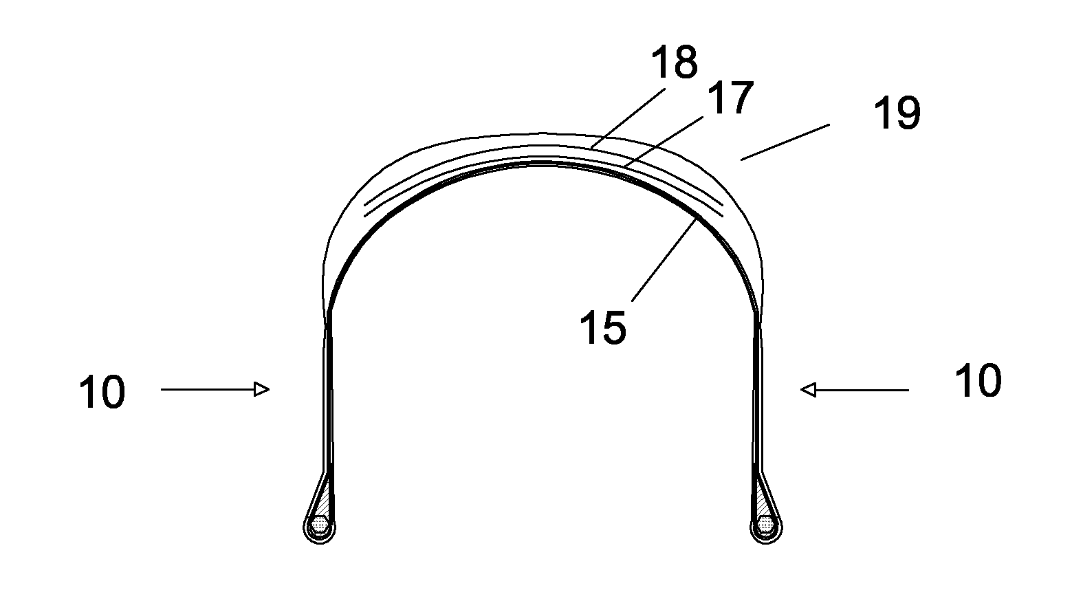
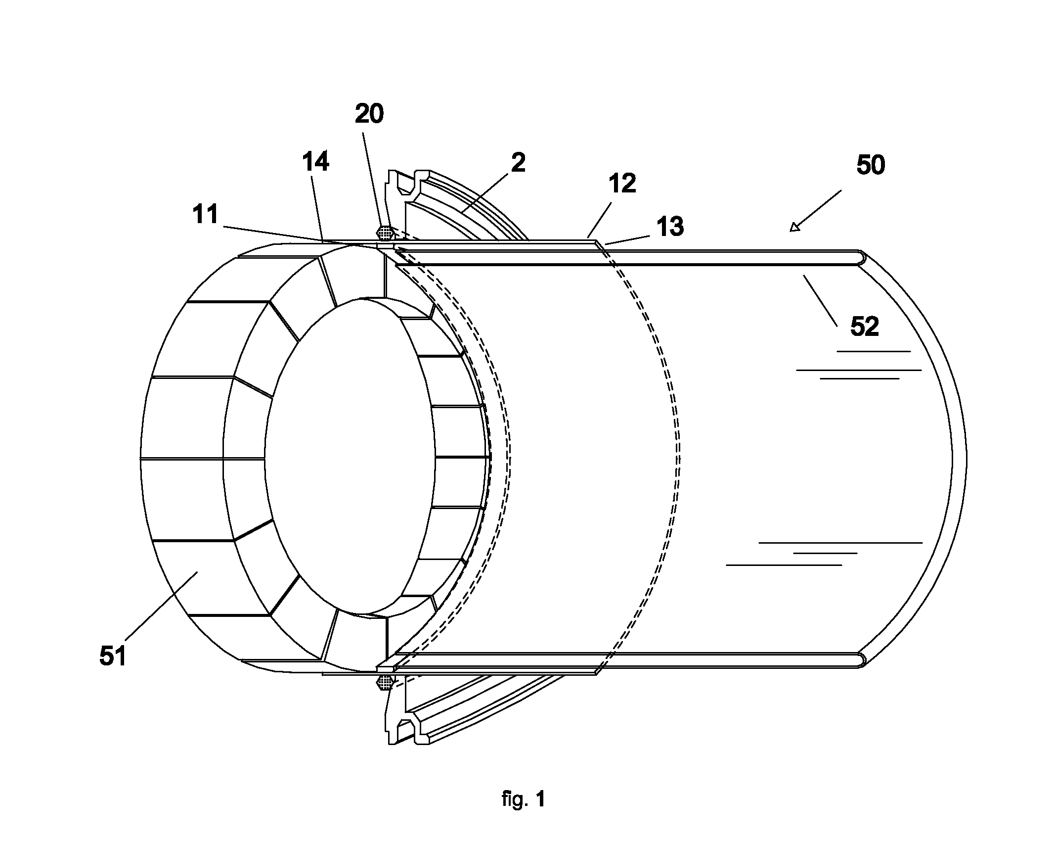
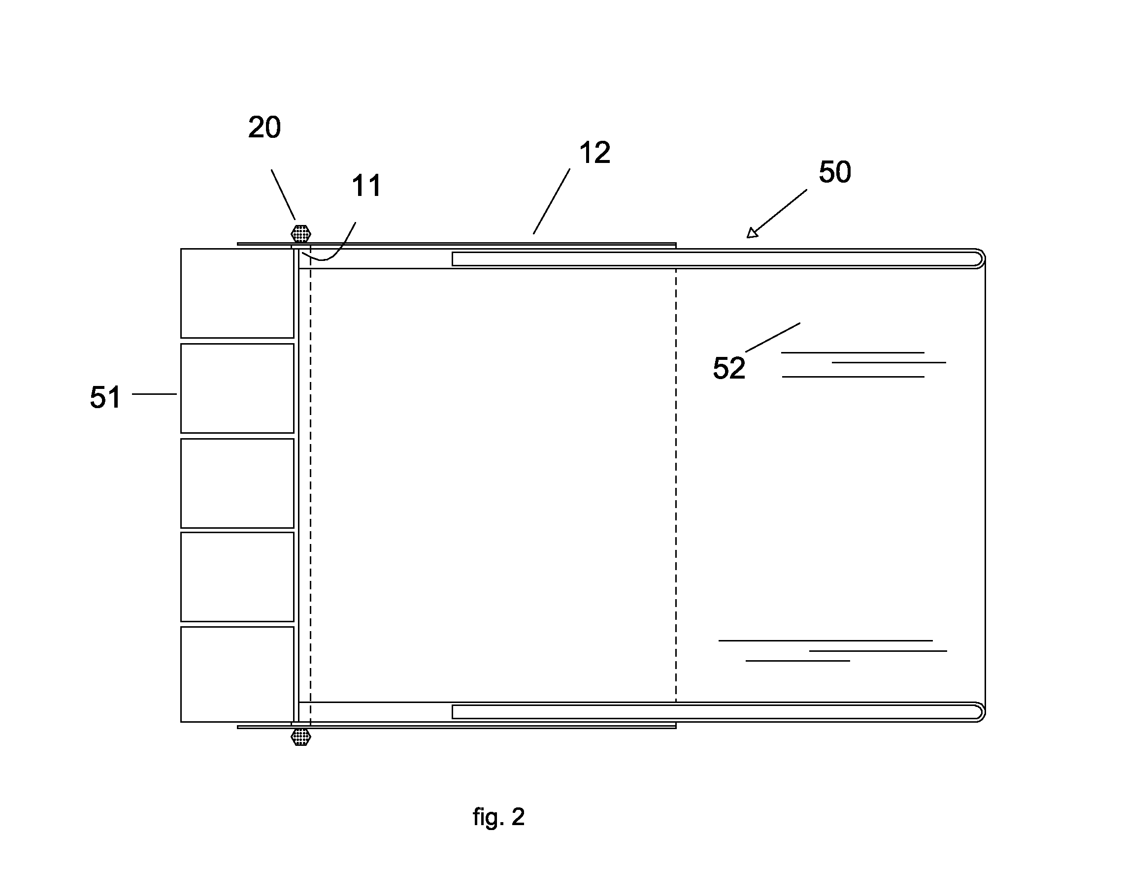
[0057]With reference to FIG. 6, a cross sectional view of the disk-shaped bead area monocomponent made according to the present invention is illustrated. As shown, the monocomponent 10 has a bead core 20. The bead core 20 is made of substantially inextensible wires wrapped around to form an annular ring. Directly above the bead core 20 is an elastomeric apex 30. The apex 30, shown in a somewhat triangular form, is positioned and provides an elastomeric spacer between the ply strip 12 and the ply turnups 14 as illustrated. The ply turnup 14 as shown extends to a turnup end 14A which is stitched directly onto the working portion or outside ply portion 12A of the ply strip 12. The ply strip 12 wrapping about the bead core 20 as shown provides the opportunity to have an inside ply ending or turnup 14 relative to the bead core 20. On the outside of the ply strip 12 is the working portion of the ply which extends to a radially outer end 13 as illustrated and affixed to the outer surface o...


PUM


Abstract

An intermediate article of manufacture formed as a first stage bead area subassembly for a split ply pneumatic tire carcass is disclosed. The bead area subassembly has an annular bead core; a bead apex; a ply strip; and preferably a sidewall affixed to the ply strip. The subassembly is formed into a disk-shaped bead area monocomponent. The ply strip is wrapped about the bead core and the apex to form a ply turnup and both the ply strip and the ply turnup extend radially outwardly from the bead core. The bead area subassembly when formed into the disk-shaped bead area monocomponent is placed on an annular holder device. The combination of the bead area monocomponent on the holder device can be stacked for storage and latter assembly into a split ply carcass. Preferably, the ply turnup can be oriented extending inside or axially inward of the bead core on final assembly to form a split ply tire having axially inside turnups. In the preferred embodiment the ply strip is reinforced by radially extending ply cords.

Description

TECHNICAL FIELD[0001]The present invention relates to pneumatic tires generally, more specifically to split ply tire constructions and their method of manufacture.BACKGROUND OF THE INVENTION[0002]A conventional radial ply tire has a single carcass ply extending between a pair of axially spaced bead cores which is wrapped about each bead core having axially outer ply turnup ends. This construction has the main working part of the ply turned inside of a bead apex forcing a curvature in the ply path when the tire is mounted onto a rim. This curvature gives the radial tire a fat bulging appearance in the tire footprint when under load.[0003]Attempts to avoid this sidewall curvature change about the bead and bead apex have led some to attempt a ply path that wraps about the bead and has the turnup end wrap inside of the bead and bead apex. In this construction the turnups are positioned inside the beads and the ply path avoids the normal curvature change. This provides a better performin...

Claims


Application Information

Patent Timeline
IPC IPC(8): B60C15/04B60C9/18B32B3/00B29D30/08B32B3/02B60C15/06B29D30/48
CPCB29D30/50B29D2030/482B29D2030/486Y10T428/21B60C9/0292B60C9/0207Y10T428/24628B60C15/0072B29D30/32B29D30/0681B29D30/72B29D2030/086B29D2030/105B29D2030/2614B29D2030/2685Y10T428/249921
Inventor WEAVER, DOUGLAS RAYMONDKITZ, STEVEN LEONARD
Owner THE GOODYEAR TIRE & RUBBER CO
Why Eureka
Try Eureka