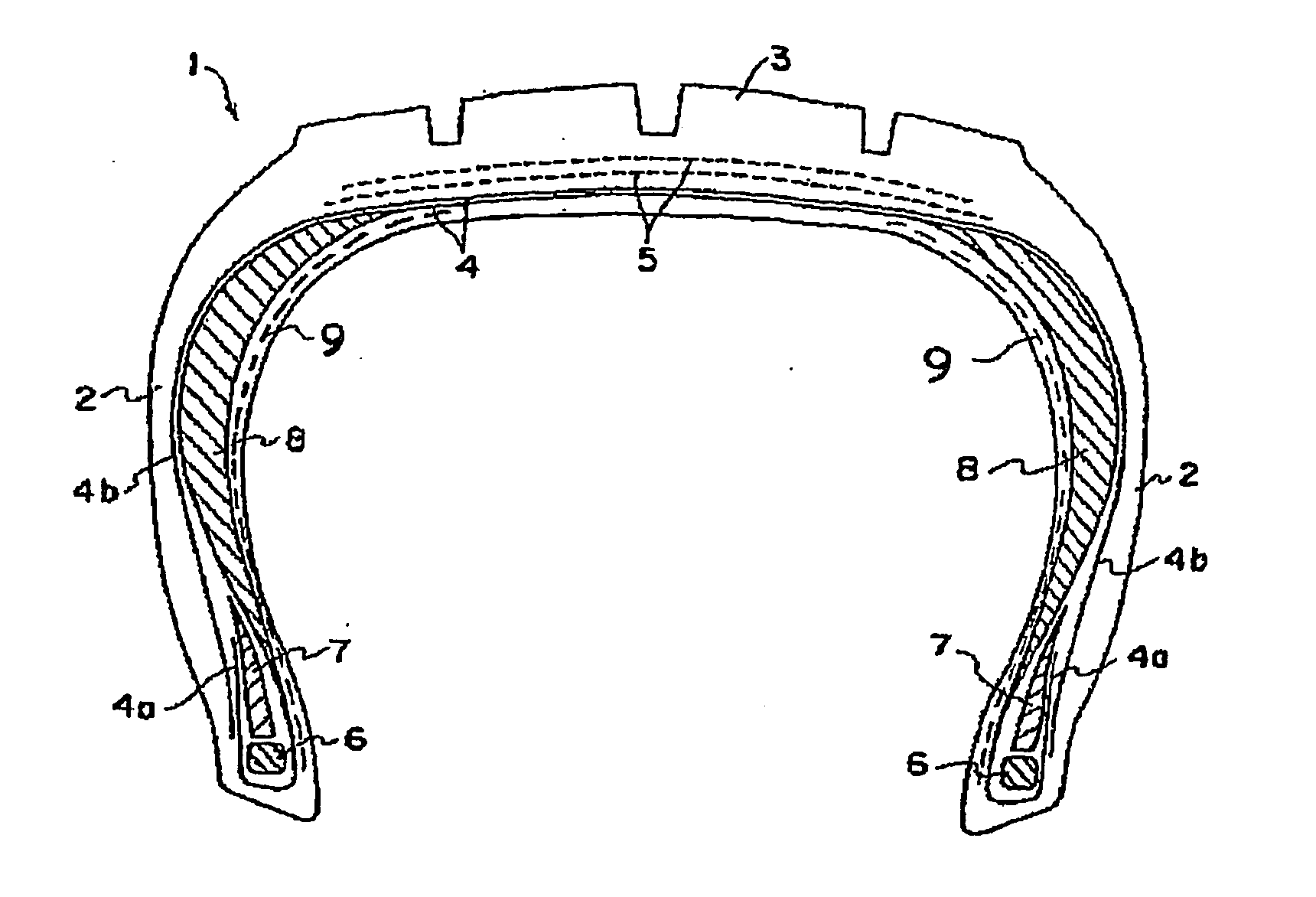
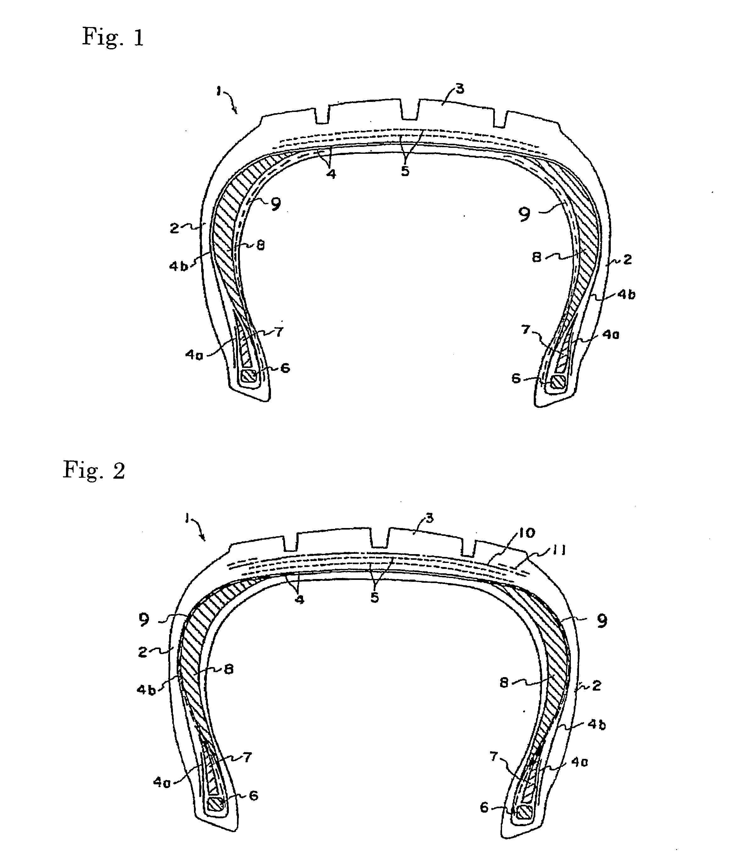
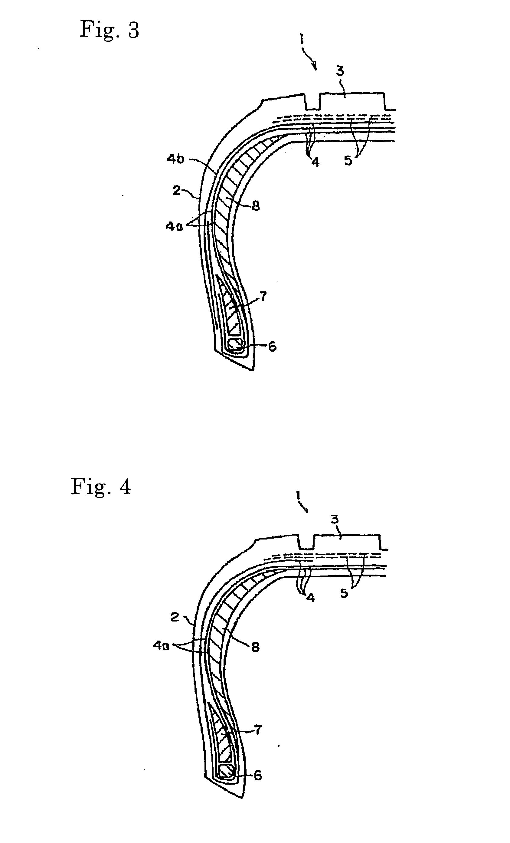
Pneumatic tire

a technology of pneumatic tires and skeleton parts, which is applied in the field of pneumatic tires, can solve the problems of reduced internal pressure of tires to atmospheric pressure, almost complete loss of tension formed in the skeleton portion of tires, and loss of braking performance and turning performance, so as to achieve excellent ride comfort and excellent durability

Inactive Publication Date: 2006-12-07
BRIDGESTONE CORP
View PDF20 Cites 24 Cited by
  • Summary
  • Abstract
  • Description
  • Claims
  • Application Information

AI Technical Summary

Benefits of technology

[0013] The present invention has, under the above circumstances, an object of providing a safety tire which enables stable driving even after the tire has a damage, and exhibits excellent run flat durability without sacrificing rolling resistance and ride comfort during driving under a normal condition.
[0043] As the fifth aspect, the present invention provides a method for exhibiting both of excellent ride comfort during driving under a condition of a normal internal pressure and excellent durability under a run flat state of a pneumatic tire, the method comprising disposing on a side wall portions of the tire a rubber member comprising a rubber composition which has a dynamic storage modulus at 50° C. in a range of 2 to 20 MPa and a minimum value of a dynamic storage modulus within a temperature range of 200 to 250° C. which is 75% or more of a dynamic storage modulus at 50° C., and the tire comprising a pair of right and left bead portions, a carcass layer disposed extending between the bead portions, a tread portion arranged at an outside of the carcass layer in a radial direction of the tire, a pair of side wall portions arranged at right and left sides of the tread portion, and at least one pair of rubber members selected from a pair of rubber members constituted with a rigid rubber and arranged in the bead portions and a pair of rubber members disposed in the side wall portions.

Problems solved by technology

If a tire which is kept at a specific internal pressure has an external damage, the air leaks to the outside through the damage and the internal pressure of the tire is reduced to atmospheric pressure, i.e., the tire falls into a flat state and the tension formed in the skeleton portion of the tire is almost entirely lost.
Therefore, the function of supporting load and the driving performance, the braking performance and the turning performance which are obtained by the tension provided by a prescribed internal pressure of the tire are also lost and a vehicle equipped with such a tire cannot be driven any more.
At such a high temperature, the breaking of crosslinked portions formed by vulcanization and the breaking of polymer chain occur in the rubber component in the above rubber composition, and as a result, the modulus of elasticity of the rubber composition decreases and the function of supporting load becomes less effective to result in increased deformation of the tire.
The increase in the deformation causes further heat generation, and the fracture limit of the side wall reinforcing layer decreases.
As a result, the tire is damaged in a relatively short period of time.
The conventional approach by considering the aspect of compounding is, however, rather limited, and therefore, the amount of the side wall reinforcing layer and / or the bead filler must be increased to surely achieve a durability distance of a certain level or longer in a driving operation under the run flat condition.
The increased spring constants bring about a marked increase of a rolling resistance and a deterioration of the ride comfort during a driving under a condition of a normal internal pressure before the internal pressure is dropped as well as bring about a marked decrease of the durability of a suspension system of a vehicle because of a large load to the suspension system.
Therefore, the above conventional technique is still less applicable to a wide use in view of adverse effects on the performance during driving under a condition of the normal internal pressure, the durability of the vehicle, the fuel economy, and the environment.
Such a tire, however, cannot endure a repeated local input which occurs between the tire and the inner supporting member during a driving under the run flat condition after puncture, and as a result thereof, the driving distance under the run flat condition is, in general, limited to about 100 to 200 km.
This technique has a further drawback in that the operation of assembling a tire with a rim after an inner supporting member is disposed to the rim is complicated and takes a long period of time.
A sufficient effect, however, has not been obtained.
The rolling resistance and the ride comfort during driving under a normal condition, however, become poor because of the increased amount of the skeleton material and this technique does not have practical values.
The tires proposed above are limited mainly to special tires or small-sized tires such as agricultural tires, tires for rally, motorcycle tires and bicycle tires.
Additionally, since the inside of the closed cells of the foamed material is set at atmospheric pressure, replacing the air set at high pressure in ordinary pneumatic tires with the foamed material is functionally insufficient.
In addition to the disadvantage resulted from the pressure inside the closed cells which is very close to atmospheric pressure, the foamed filler shows a large energy loss attributable to the inter-molecular hydrogen bonding between urethane linkages and also shows a high self-heat generation because the foamed material is made of polyurethane.
Thus, when the inside of a tire is filled with a foamed material made of polyurethane, repeated deformation by rotation of the tire causes the foamed material to generate heat, thereby drastically decreasing the durability.
Moreover, since a raw material which is difficult to form closed cells is used, the formed cells are easily communicated with each other, and hence it is difficult that gas is held within the material.
In particular, the desired internal pressure cannot be maintained during driving after the tire is damaged.

Method used


Image

  • Pneumatic tire
  • Pneumatic tire
  • Pneumatic tire

Examples


examples

[0172] The present invention will be described more specifically with reference to examples in the following. However, the present invention is not limited to the examples.

[0173] Various measurements were conducted by the following methods.

(1) Microstructure of a Polymer

[0174] The content of vinyl linkages in the portion of conjugated diene units (the 1,2-structure in the butadiene portion) was obtained by the infrared spectroscopy (the Morero's method).

(2) Physical Properties of a Vulcanized Rubber Composition [Dynamic Storage Modulus (E′)]

[0175] From a slab sheet having a thickness of 2 mm which was obtained by vulcanizing a rubber composition under the condition of 160° C. for 12 minutes, a sheet having a width of 5 mm and a length of 40 mm was cut out and used as the sample. Using the obtained sample, the dynamic storage modulus (E′) was measured under the condition of a distance between clamps of 10 mm, an initial strain of 200 micrometers (microns), a dynamic strain of 1...

preparation examples 1 to 18

BR-based polymers A, B, I to X; Batch Polymerization

[0218] Into a 8 liter pressure-resistant reactor having a jacket for adjusting the temperature, the reactor which had been dried and purged with nitrogen, 3 kg of cyclohexane, 500 g of butadiene monomer and 0.225 mmole of ditetrahydrofurylpropane (DTHFP) were placed. After 4.5 mmole of n-butyllithium (BuLi) was added to the resultant mixture, the polymerization was allowed to proceed at an initial temperature of 40° C. for 1 hour. The polymerization was allowed to proceed while the temperature was elevated and the temperature in the jacket was adjusted so that the final temperature of the reaction system did not exceed 75° C. The polymerization system was completely homogeneous and transparent without precipitates from the start to the end of the polymerization. The conversion of the polymerization was about 100%.

[0219] To the obtained polymerization system, 0.11 ml of SnCl4 (TTC, a 1 M cyclohexane solution) was added as the end ...

preparation examples 19 to 21

BR-Based Polymers Y, Z and AA; Batch Polymerization, Using a Modifying Initiator

[0223] Into a 8 liter pressure-resistant reactor having a jacket for adjusting the temperature, the reactor which had been dried and purged with nitrogen, 3 kg of cyclohexane, 500 g of butadiene monomer and 1.6 mmole of ditetrahydrofurylpropane (DTHFP) were placed. After 4 mmole of n-butyllithium (BuLi) was added to the resultant mixture, 0.8 mmole of hexamethyleneimine (HMI) was quickly added and the polymerization was allowed to proceed at an initial temperature of 40° C. for 1 hour. The polymerization was allowed to proceed while the temperature was elevated and the temperature in the jacket was adjusted so that the final temperature of the reaction system did not exceed 75° C. The polymerization system was completely homogeneous and transparent without precipitates from the start to the end of the polymerization. The conversion of the polymerization was about 100%.

[0224] To the obtained polymerizat...


PUM

PropertyMeasurementUnit
Temperatureaaaaaaaaaa
Fractionaaaaaaaaaa

Abstract

A pneumatic tire which comprises a pair of right and left bead portions, a carcass layer disposed extending between the bead portions, a tread portion arranged at an outside of the carcass layer in a radial direction of the tire, a pair of side wall portions arranged at right and left sides of the tread portion and at least one pair of rubber members selected from a pair of rubber members constituted with a rigid rubber and arranged in the bead portions and a pair of rubber members disposed in the side wall portions, wherein at least one pair of rubber members selected from a pair of rubber members arranged in the bead portions and a pair of rubber members disposed in the side wall portions are constituted with rubber composition having a minimum value of a dynamic storage modulus within a temperature range of 200 to 250° C. which is 75% of a dynamic storage modulus at 50° C. or more.

Description

TECHNICAL FIELD [0001] The present invention relates to a pneumatic tire which is not affected by a puncture caused by an external damage, etc. and, more particularly, to a safety pneumatic tire which simultaneously exhibits both of an excellent durability during driving under a damaged condition (run flat durability) and an excellent ride comfort under a condition of the normal internal pressure (ride comfort). BACKGROUND ART [0002] In general, in a pneumatic tire, tension is generated in the skeleton portion of the tire such as carcass, belt and the like by enclosing air in the inside of the tire so as to give a pressure of about 200 to 400 kPa in terms of the absolute pressure based on the vacuum (hereinafter simply referred to as “internal pressure”). The tire can be deformed by a force input into the tire and the deformation can be recovered by the generated tension. In other words, by maintaining the internal pressure of a tire within a specific range, a prescribed tension is ...

Claims


Application Information

Patent Timeline
IPC IPC(8): B60C17/00B60C1/00B60C15/06C08L21/00
CPCB60C1/0025Y10T152/10864C08K5/3415C08K5/39C08K5/41C08L21/00Y10T152/10846B60C2017/0063B60C17/0009B60C15/0603B60C2001/0033B60C2001/0058
Inventor TERATANI, HIROYUKIMOTOFUSA, SHINICHIKONDO, HAJIMENISHIKAWA, TOMOHISAKUSANO, YUKIHIROZUIGYOU, YUGO
Owner BRIDGESTONE CORP
Why Eureka
Try Eureka