Optical unit, vehicle monitor, and obstruction detector

a technology of optical units and detectors, applied in the field of optical units, can solve the problems of erronely detecting the light of reflective objects such as roadside delineators or signboards, and achieve the effect of efficient use of ligh

Active Publication Date: 2013-02-14
KOITO MFG CO LTD
View PDF8 Cites 56 Cited by
  • Summary
  • Abstract
  • Description
  • Claims
  • Application Information

AI Technical Summary

Benefits of technology

[0014]The invention has been made in consideration of these circumstances, and an object of the invention is to provide a technique related to an optical unit that can efficiently use the light of a light source for illumination.

Problems solved by technology

However, this method has a possibility that the light reflected by a reflective object, such as a roadside delineator or a signboard, is erroneously detected as the light of a lamp of a vehicle.

Method used


Image

  • Optical unit, vehicle monitor, and obstruction detector
  • Optical unit, vehicle monitor, and obstruction detector
  • Optical unit, vehicle monitor, and obstruction detector

Examples


first embodiment

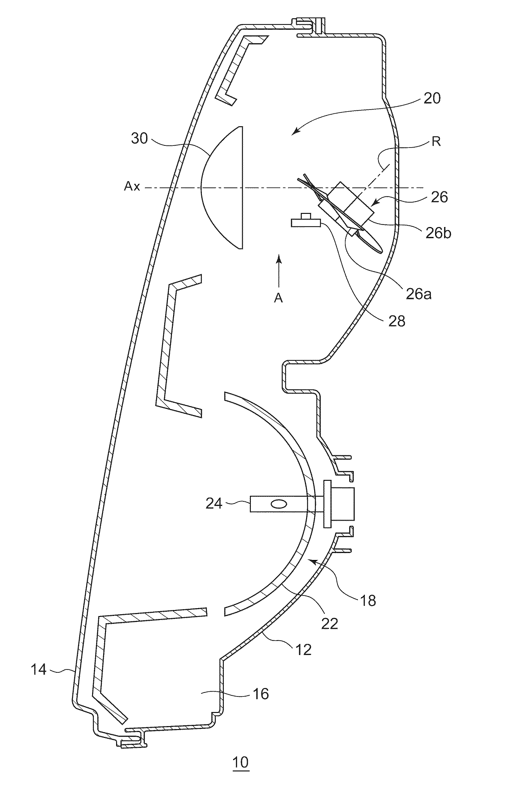
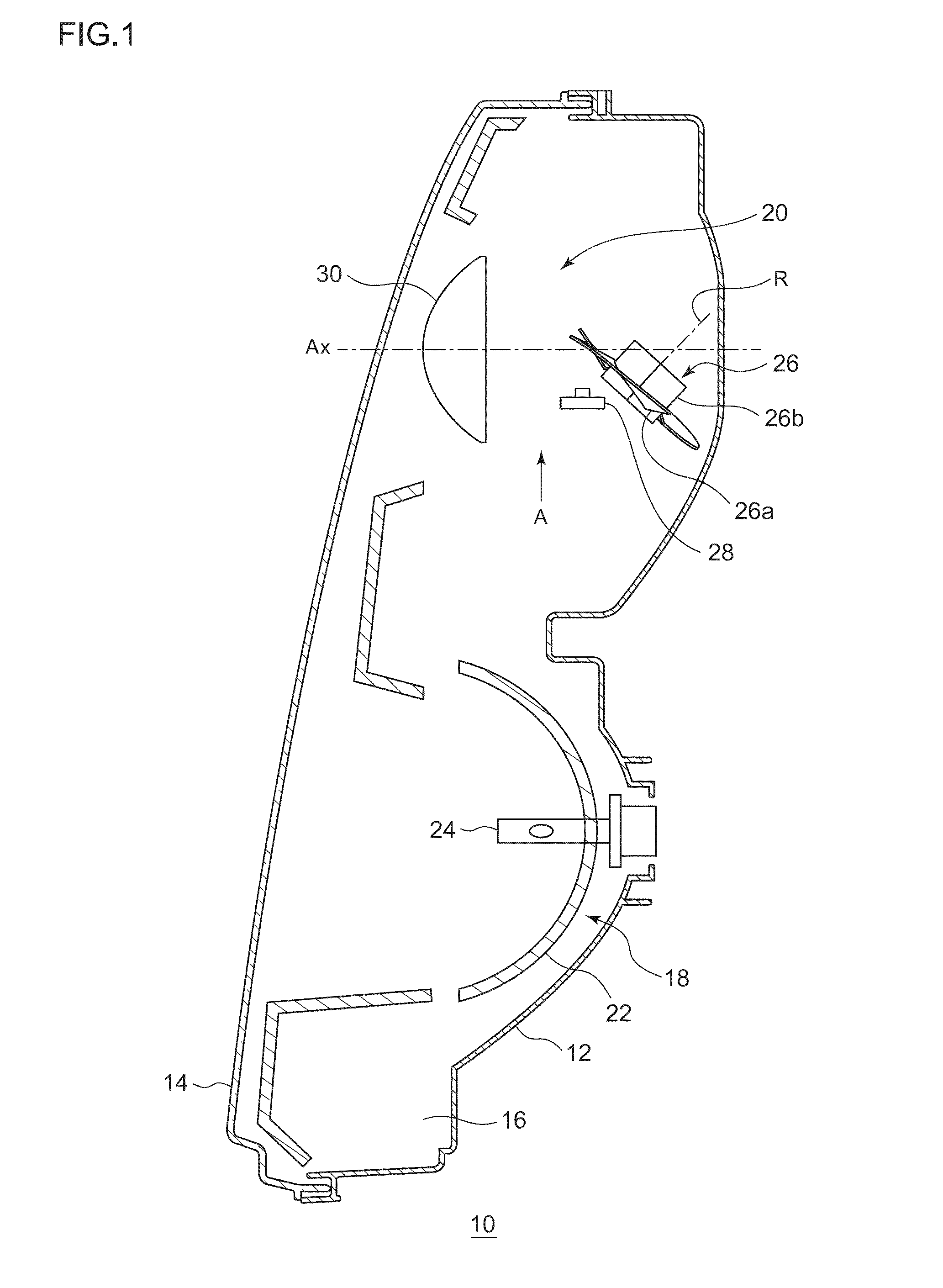
[0095]FIG. 1 is a horizontal cross-sectional view of a vehicle headlight according to this embodiment. A vehicle headlight 10 is a right headlight that is mounted on the right side of the front end portion of an automobile, and has the same structure as a headlight mounted on the left side except that the vehicle headlight 10 is symmetrical to the headlight mounted on the left side. For this reason, in the following description, the right vehicle headlight 10 will be described in detail and the description of the left vehicle headlight will not be described.

[0096]As illustrated in FIG. 1, the vehicle headlight 10 includes a lamp body 12 that includes a recess opened forward. A front opening of the lamp body 12 is covered with a transparent front cover 14, so that a lamp chamber 16 is formed. The lamp chamber 16 functions as a space in which two lamp units 18 and 20 are received so as to be disposed side by side in the width direction of a vehicle.

[0097]Among these lamp units, an out...

second embodiment

[0115]When the light of a LED is reflected and is projected forward by a projection lens, the shape of a projection image does not necessarily correspond to the shape of a light emitting surface of the LED. FIG. 7(a) is a view showing a projection image when the light of the LED is reflected by a plane mirror and is projected by an aspherical lens, FIG. 7(b) is a view showing a projection image of the vehicle headlight according to the first embodiment, and FIG. 7(c) is a view showing a projection image of a vehicle headlight according to a second embodiment.

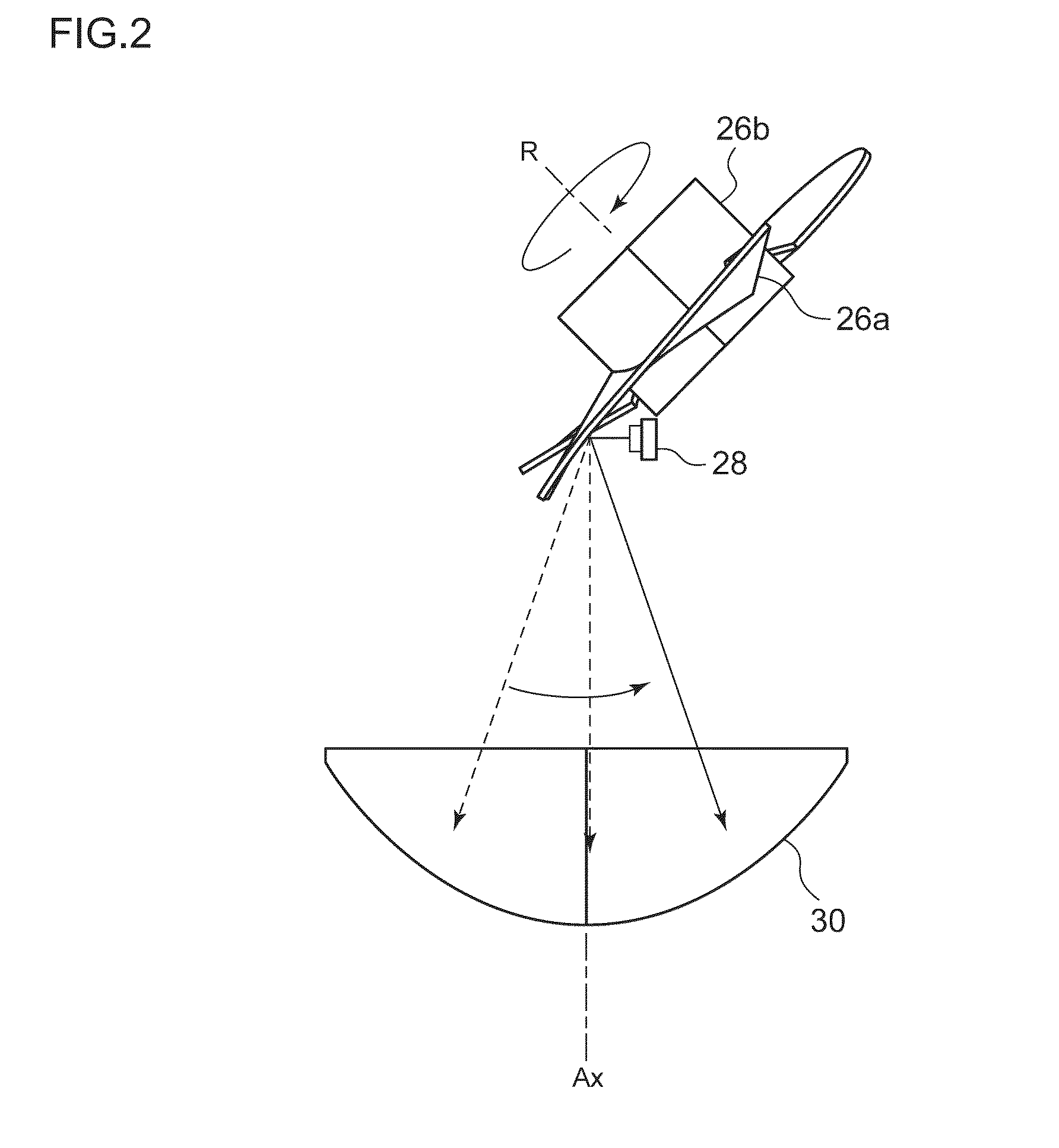
[0116]If a reflecting surface is a flat surface, a projection image is similar to the shape of the light emitting surface of the LED as illustrated in FIG. 7(a). However, since the blades 26a forming the reflecting surface are twisted in the rotating reflector 26 according to the first embodiment, a projection image is distorted as illustrated in FIG. 7(b). Specifically, in the first embodiment, the projection image is blurred (...

third embodiment

[0122]The optical unit according to the second embodiment can correct the shape of the projection image to a shape close to a rectangular shape, which is the shape of a light source, by the function of the free curved-surface lens. However, when a light distribution pattern is formed through the scanning of the projection image corrected in this way, there is still room for improvement.

[0123]FIG. 11(a) is a view showing an irradiation pattern that is formed by the optical unit according to the second embodiment, and FIG. 11(b) is a view showing a state where the projection images formed by the optical unit according to the second embodiment are combined. FIG. 12(a) is a view showing a state where a compound parabolic concentrator32 including the LED 28 is disposed so that the longitudinal direction of the compound parabolic concentrator 32 is parallel to a vertical direction, and FIG. 12(b) is a view showing a state where the compound parabolic concentrator 32 is disposed so that th...


PUM


Abstract

Disclosed is an optical unit wherein a rotating reflector rotates about a rotation axis in one direction, while reflecting light emitted from a light source. The rotating reflector is provided with a reflecting surface such that the light reflected by the rotating reflector, while rotating, forms a desired light distribution pattern, said light having been emitted from the light source. The light source is composed of light emitting elements. The rotation axis is provided within a plane that includes an optical axis and the light source. The rotating reflector is provided with, on the periphery of the rotation axis, a blade that functions as the reflecting surface.

Description

CROSS-REFERENCE TO RELATED APPLICATIONS[0001]This application is based upon and claims the benefit of priority from the prior Japanese Patent Application No. 2010-092123, filed on Apr. 13, 2010, Japanese Patent Application No. 2010-092124, filed on Apr. 13, 2010, Japanese Patent Application No. 2010-097946, filed on Apr. 21, 2010, Japanese Patent Application No. 2010-110139, filed on May 12, 2010, and Japanese Patent Application No. 2011-021905, filed on Feb. 3, 2011, the entire contents of which are incorporated herein by reference.BACKGROUND OF THE INVENTION[0002]1. Field of the Invention[0003]The present invention relates to an optical unit, and more particularly, to an optical unit used for a vehicle lamp. Further, the present invention relates to a vehicle monitor. Furthermore, the present invention relates to an obstruction detector.[0004]2. Description of the Related Art[0005]In recent years, a vehicle headlight that includes a mirror and can reciprocatively turn the mirror h...

Claims


Application Information

Patent Timeline
Patent Type & Authority Applications(United States)
IPC IPC(8): H04N7/18F21V13/06F21V7/20F21V7/00F21V29/505G01S13/931
CPCB60Q1/143B60Q2300/056B60Q2300/3321B60Q2300/41F21S48/1394B60Q2300/45F21S48/1159F21S48/1163F21S48/1757B60Q2300/42F21S41/675F21S41/25F21S45/43F21S41/141F21V33/0052F21W2102/00F21W2107/10F21S41/155F21S41/36F21S41/37F21S41/365G01S13/426G01S13/931G01S2013/93277F21S41/153F21S41/148F21S41/147G06V20/584B60R11/04G01S13/88B60Q2300/40H04N7/183
Inventor YAMAMURA, SATOSHI
Owner KOITO MFG CO LTD
Why Eureka
Try Eureka