Mounting rail for a lamp

Active Publication Date: 2013-02-14
LED LINEAR
View PDF3 Cites 16 Cited by
  • Summary
  • Abstract
  • Description
  • Claims
  • Application Information

AI Technical Summary

Benefits of technology

[0006]It is therefore an object of the present

Problems solved by technology

In adapter profiles known in prior art it is felt to be disadvantageous that they essentially have only o

Method used


Image

  • Mounting rail for a lamp
  • Mounting rail for a lamp
  • Mounting rail for a lamp

Examples


Embodiment Construction

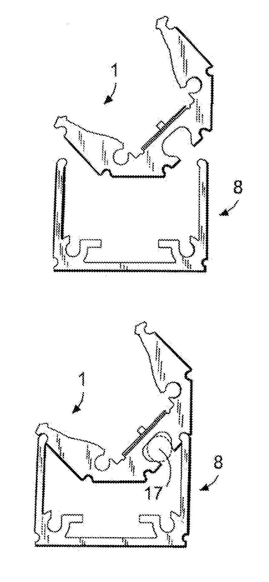
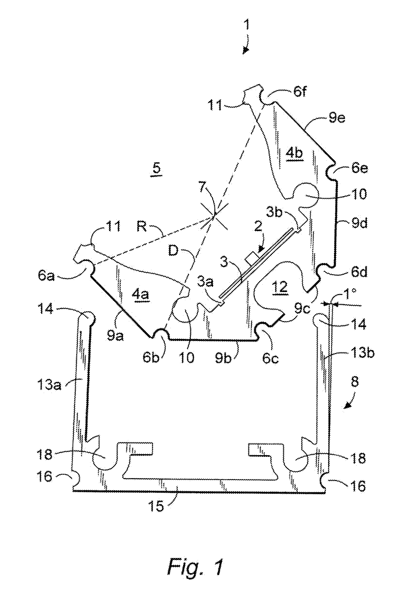
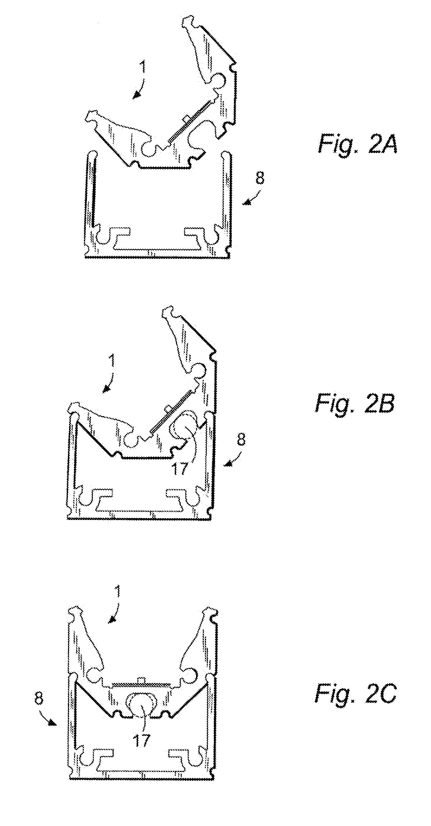
[0042]FIG. 1 shows an adapter profile 1 and a profiled mounting rail 8 before they have been fitted and locked together. The adapter profile 1, which is an extruded part and basically of U-section with a polygonal outside shape, defines an internal planar mounting face 3 formed with two outwardly open parallel grooves 3a and 3b between which is mounted an LED strip 2.

[0043]The adapter profile 1, which is centered on a longitudinal axis 7 extending perpendicular to the view plane of FIG. 1, has a pair of transversely spaced and longitudinally extending brackets 4a and 4b that flank the face 3 and that have outer edges that define a longitudinally extending opening 5 open transversely away from the face 3 with the LED lamp 2.

[0044]The outer surface of this profile 1 is formed by five planar faces 9a-9e defined between semicircular outwardly open grooves 6a-6f each extending a full longitudinal length of the profile. The grooves 6a-6f are all centered on respective axes that are parall...


PUM


Abstract

A generally U-section adapter profile extending along a longitudinal axis forms a longitudinally extending and transversely open cavity and has an outer surface formed with an array of at least three longitudinally extending and radially outwardly directed outer mounting formations radially spaced from the longitudinal axis and angularly spaced around the longitudinal axis. An elongated light emitter is provided in the cavity. A generally U-section mounting rail extending parallel to the axis opens radially toward the axis and has two side walls formed with inwardly directed and longitudinally extending inner mounting formations generally complementary to the outer formations and spaced so that the profile can be fitted to the rail in at least two different positions in each of which the two inner formations of the rail engage in two of the outer formations of the profile.

Description

FIELD OF THE INVENTION[0001]The present invention relates to ceiling- or wall-mount lamp. More particularly this invention concerns a mounting rail and adapter assembly of such a lamp.BACKGROUND OF THE INVENTION[0002]Light fixtures, in particular light-emitting-diode (LED) strips with a mounting face for light fixtures located inside the adapter profile that is located between two spaced and confronting walls and diametrically opposed to an opening of the adapter profile.[0003]Adapter profiles of for use in light fixtures are known in prior art. In a simple case, such an adapter profile can, for example, be a longitudinally extending extruded profile of U-section. Thereby the inner surface of the base of such a profile forms a mounting face for the illuminant or light emitter that extends between two side walls or brackets extending from the base.[0004]For example, this type of adapter profile is in combination with LED strips in which a number of individual LEDs are lined up next t...

Claims


Application Information

Patent Timeline
IPC IPC(8): F21V21/00
CPCF21V19/00F21V15/013F21V21/025F21V17/104F21V17/16F21V17/002
Inventor FORTEZA, GABRIELA VIDALKRAMER, MICHAEL
Owner LED LINEAR
Why Eureka
Try Eureka