Mounting rail for a lamp
- Summary
- Abstract
- Description
- Claims
- Application Information
AI Technical Summary
Benefits of technology
Problems solved by technology
Method used
Image
Examples
Embodiment Construction
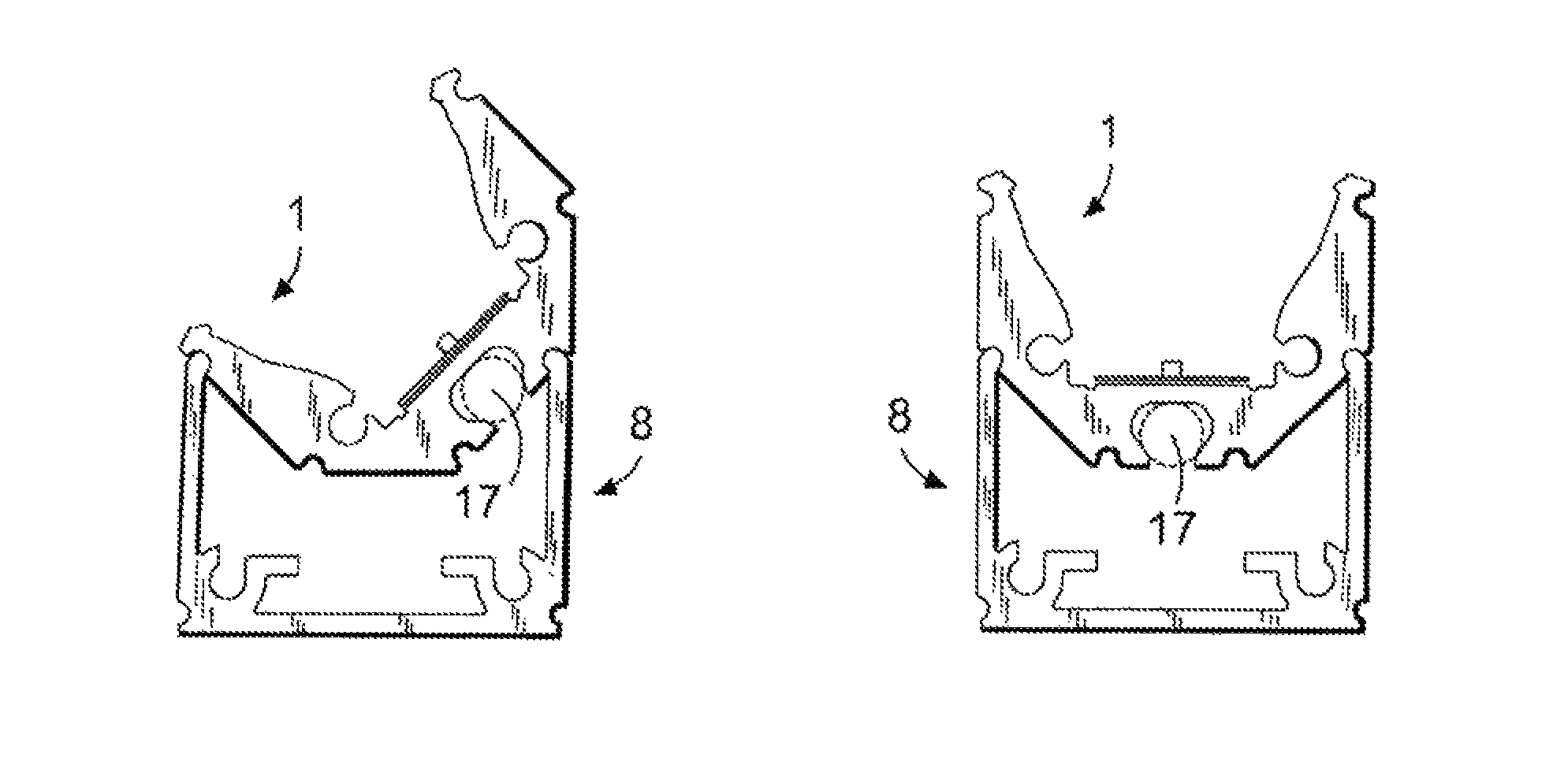
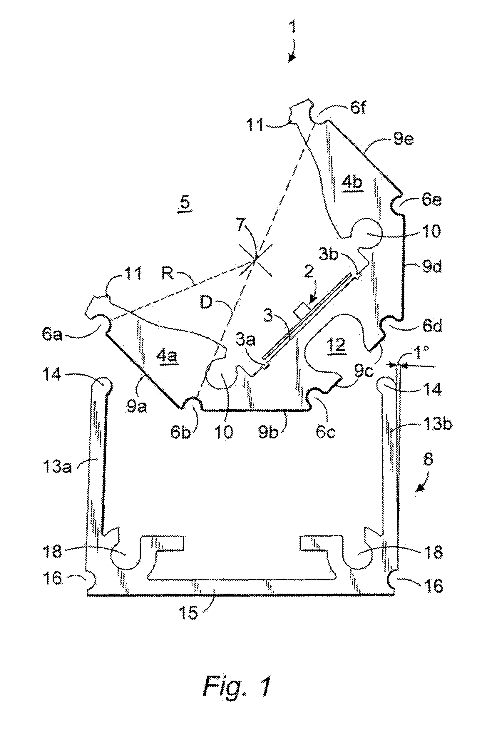
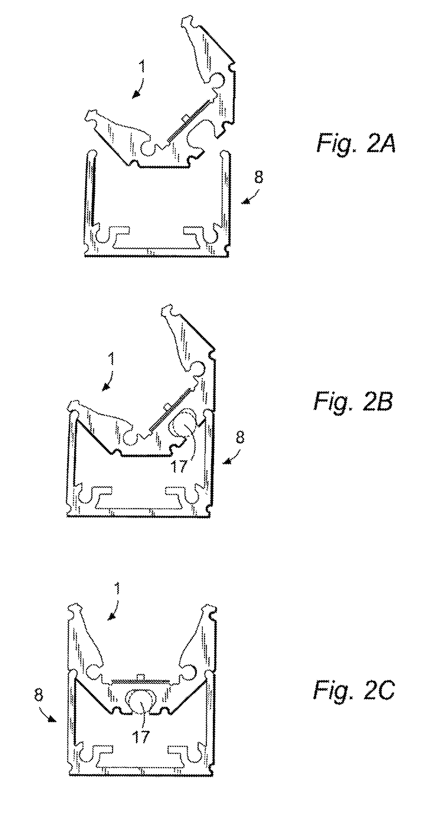
[0043]FIG. 1 shows an adapter profile 1 and a profiled mounting rail 8 before they have been fitted and locked together. The adapter profile 1, which is an extruded part and basically of U-section with a polygonal outside shape, defines an internal planar mounting face 3 formed with two outwardly open parallel grooves 3a and 3b between which is mounted an LED strip 2.
[0044]The adapter profile 1, which is centered on a longitudinal axis 7 extending perpendicular to the view plane of FIG. 1, has a pair of transversely spaced and longitudinally extending brackets 4a and 4b that flank the face 3 and that have outer edges that define a longitudinally extending opening 5 open transversely away from the face 3 with the LED lamp 2.
[0045]The outer surface of this profile 1 is formed by five planar faces 9a-9e defined between semicircular outwardly open grooves 6a-6f each extending a full longitudinal length of the profile. The grooves 6a-6f are all centered on respective axes that are parall...
PUM
 Abstract
Description
Claims
Application Information
 - R&D
- Intellectual Property
- Life Sciences
- Materials
- Tech Scout
- Unparalleled Data Quality
- Higher Quality Content
- 60% Fewer Hallucinations
Browse by: Latest US Patents, China's latest patents, Technical Efficacy Thesaurus, Application Domain, Technology Topic, Popular Technical Reports.
© 2025 PatSnap. All rights reserved.Legal|Privacy policy|Modern Slavery Act Transparency Statement|Sitemap|About US| Contact US: help@patsnap.com


