Construction control method for large direct-buried steel anchor fluke embedded part

A control method and technology of embedded parts, which are applied in the processing of building materials, construction, building structure, etc., can solve the problems of shortening installation time and low accuracy, and achieve shortening installation time, simple method, and simple installation and positioning process. Effect

Active Publication Date: 2014-01-01
CHINA MCC5 GROUP CORP
View PDF6 Cites 10 Cited by
  • Summary
  • Abstract
  • Description
  • Claims
  • Application Information

AI Technical Summary

Problems solved by technology

[0006] The purpose of the present invention is to overcome the problem of low accuracy of existing large-scale steel anchor fluke embedded parts during construction, and design a construction control method for large-scale direct-buried steel anchor fluke embedded parts. According to the construction control method, it can Reduce installation time and improve installation accuracy

Method used


Image

  • Construction control method for large direct-buried steel anchor fluke embedded part
  • Construction control method for large direct-buried steel anchor fluke embedded part
  • Construction control method for large direct-buried steel anchor fluke embedded part

Examples


Embodiment 1

[0032] Such as image 3 , Figure 4 , Figure 5 , Figure 6 As shown, the construction control method of large directly buried steel anchor fluke embedded parts includes the following steps:

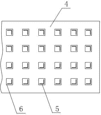
[0033] (a) Set up corbel reinforcement cages or frame beams, and pour concrete under the corbel reinforcement cages 13 or frame beams, and bury the bottom ends of several supporting angle steels 10 in the concrete, and the height of the tops of the supporting angle steels is higher than that of the corbel reinforcement cages Or the upper surface of the frame beam, after the reinforcement binding of the corbel reinforcement cage 13 or the frame beam is completed, put out the elevation control point 12 of the bottom surface of the embedded steel plate 4 on each support angle steel 10 with a level gauge, then use flame cutting to The angle steel 11 above the elevation control point is cut off. In this way, after the embedded part is installed, the top of the supporting angle steel 10 ca...

Embodiment 2

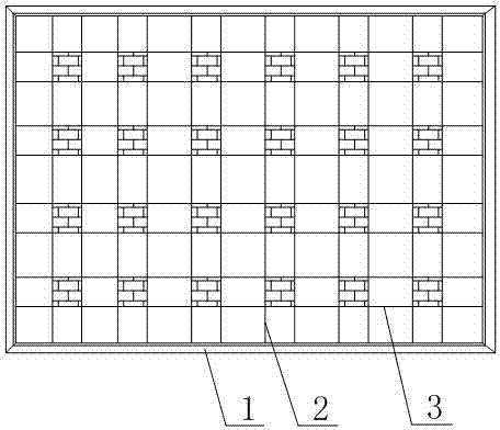
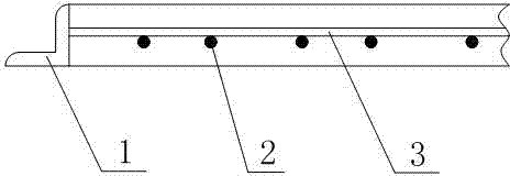
[0039] Such as figure 1 , figure 2 As shown, on the basis of Example 1, the positioning frame includes a rectangular structure composed of four positioning angle steels 1 welded end to end in sequence and a positioning device arranged inside the rectangular structure, both ends of the positioning device are connected to the positioning angle steel 1 . The edge width of the positioning angle steel 1 is 50mm and the thickness is 3mm. The positioning angle steel 1 of this size is used as a preferred size, and other sizes can also be selected according to the situation of the abandoned angle steel on each construction site. The size of the rectangle formed by the positioning angle steel 1 is the same as the size of the embedded part, and the outer wall of the rectangle is correspondingly arranged in the same plane as the outer wall of the corbel reinforcement cage, so that when the iron wire is tightened to form the position of the steel anchor, it can A uniform distribution is...


PUM


Abstract

The invention discloses a construction control method for a large direct-buried steel anchor fluke embedded part. The construction control method comprises the steps of pouring concrete under a corbel steel bar cage or a frame beam, burying the bottom ends of supporting angle steel in the concrete, enabling the top ends of the supporting angle steel to be higher than the upper surface of the corbel steel bar cage or the frame beam, using a leveling instrument to mark the height of the bottom face of an embedded part steel plate on each angle steel and then cutting off redundant portions; placing a positioning frame on the corbel steel bar cage, enabling four corners to be welded and fixed with the corbel steel bar cage through electric welding, placing a piece of square steel slightly larger than an anchor plate into one hole after the hole is adjusted, sequentially adjusting steel bars at the anchor fluke positions, hoisting the embedded part to the position right above the installing position and slowly placing the embedded part on the supporting angle steel, wherein the bottom of the embedded part is in direct contact with the top ends of the supporting angle steel. By adopting the construction control method, the installing time can be shortened, and the installing accuracy can be improved.

Description

technical field [0001] The invention relates to a method, in particular to a construction control method for a large direct-buried steel anchor claw pre-embedded part, which belongs to the construction field. Background technique [0002] The steel structure truss is located on the anti-seismic support, and the anti-seismic support is connected to the concrete structure through embedded parts. The embedded part is composed of a steel plate, an angle steel vertically arranged on the steel plate, and an anchor plate fixed on the end face of the angle steel. Due to the large load and the large size of the embedded part, the largest reaches 2000×5500. The legs are cast into shape in one pass. The embedded parts are not only large in size, but also special in anchor claws. There are 48 ∠125×14 angle steels, and 180×180 anchor plates are installed at the ends of the angle steels. Only 100. To accurately locate the embedded parts, the position of the anchor fluke can be changed ...

Claims


Application Information

Patent Timeline
Patent Type & Authority Applications(China)
IPC IPC(8): E04G21/00E04G21/18
Inventor 陈文渝蒋松甫李骑兵
Owner CHINA MCC5 GROUP CORP
Why Eureka
Try Eureka