Micro LED color display device

A color display device, red technology, applied in the direction of semiconductor devices, static indicators, electric solid devices, etc., can solve the problem of large chromaticity differences, green color chromaticity uniformity needs to be improved, green color stability is not easy to control, etc. problem, to achieve the effect of easy specification control, easy control of stability, and improvement of display quality

Inactive Publication Date: 2017-08-18
TCL CHINA STAR OPTOELECTRONICS TECH CO LTD
View PDF6 Cites 23 Cited by
  • Summary
  • Abstract
  • Description
  • Claims
  • Application Information

AI Technical Summary

Problems solved by technology

[0005] see figure 1 , through calculation, it is found that for adjacent 3 to 4 Bin LEDs, the chromaticity difference of the green LED is the largest: when the peak wavelength is shifted by 2nm, the x chromaticity difference G△x of the green LED exceeds 0.01, while a Bin The peak wavelength range of micro LEDs is often 2.5nm, which means that for Micro LED color display devices, the stability of green color is not easy to control, and the chromaticity uniformity of green color needs to be improved

Method used


Image

  • Micro LED color display device
  • Micro LED color display device
  • Micro LED color display device

Examples


no. 1 example

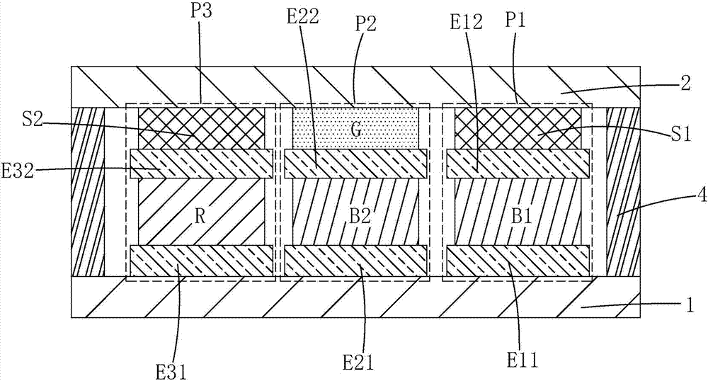
[0030] The invention provides a Micro LED color display device. figure 2 Shown is the first embodiment of the Micro LED color display device of the present invention, including a driving substrate 1, a packaging substrate 2 opposite to the driving substrate 1, and an array between the driving substrate 1 and the packaging substrate 2. A plurality of blue sub-pixels P1 , green sub-pixels P2 , and red sub-pixels P3 arranged in a formula, and a support 4 disposed between the driving substrate 1 and the packaging substrate 2 .

[0031] The blue sub-pixel P1 includes a first lower pixel electrode E11 disposed on the driving substrate 1, a first upper pixel electrode E12 disposed opposite to the first lower pixel electrode E11, and sandwiched between the first lower pixel electrode E11. The first blue LED B1 between the lower pixel electrode E11 and the first upper pixel electrode E12, and the first transparent spacer S1 arranged between the first upper pixel electrode E12 and the ...


PUM


Abstract

The invention provides a Micro LED color display device. A green-color conversion layer (G) is simulated to give out light so as to substitute a green LED by employing a short-wavelength second blue LED (B2) in a green sub-pixel (P2), the second blue LED (B2) is relatively stable, the chromaticity of green color can be controlled by controlling accuracy of a coating thickness of the green-color conversion layer (G), the accuracy control of the coating thickness is easier than specification control of the green LED, the chromaticity uniformity can be relatively good, the stability of the green color is easy to control, and the display quality is improved.

Description

technical field [0001] The present invention relates to the field of display technology, in particular to a Micro LED color display device. Background technique [0002] With the rapid development of wearable display devices, micro light emitting diode (Micro LED, uLED) technology has emerged. Micro LED technology, that is, LED miniaturization and matrix technology, refers to a high-density micro-sized LED array integrated on a chip. The power consumption of Micro LED is much smaller than that of Liquid Crystal Display (LCD), and it is self-illuminating like Organic Light-Emitting Diode (OLED), which can reduce the distance between pixels from the millimeter level to the micron level , the color saturation is close to that of OLED, so many manufacturers regard Micro LED as the next-generation display technology. [0003] The existing technology uses the Micro Transfer Print (Micro Transfer Print) method to make Micro LED arrays: after the LED bare chip (Bare Chip) is separ...

Claims


Application Information

Patent Timeline
Patent Type & Authority Applications(China)
IPC IPC(8): H01L27/15H01L33/50
CPCH01L27/156H01L33/505H01L33/507H01L25/0753H01L33/501G02F2201/123G09G3/2074G09G3/32
Inventor 陈黎暄李泳锐
Owner TCL CHINA STAR OPTOELECTRONICS TECH CO LTD
Why Eureka
Try Eureka