Communication method for monitoring pipelines

a communication method and pipeline technology, applied in the direction of resistance/reactance/impedence, instruments, measurement devices, etc., can solve the problems that the approach has not yet been possible, and achieve the effect of low cost, low power requirements, and low cos

Active Publication Date: 2013-02-21
GAS TECH INST
View PDF14 Cites 29 Cited by
  • Summary
  • Abstract
  • Description
  • Claims
  • Application Information

AI Technical Summary

Benefits of technology

[0015]The system by which the method of this invention may be implemented comprises three primary components—an interrogator which superimposes a continuous alternating electrical current (also referred to herein as a carrier current) onto the pipeline and detects the modulated signal from the sensor, known as backscatter modulation, the pipeline which conducts the continuously present carrier current, and the sensors which measure a parameter about the pipeline and communicate information about the measured parameter back to the interrogator. In accordance with a particularly preferred embodiment, the sensors are radio frequency identification (RFID) tag sensors disposed in the ground at a distance sufficient from the pipeline to enable monitoring of the pipeline in accordance with the designated purpose of the sensor, e.g. pipeline location, pipeline leakage, etc. Use of the system for implementation of the method of this invention provides the benefits of a network of continuously active sensors buried along the pipeline right-of-way, a communication means for collecting the sensor data, a continuously present locating signal on the pipeline or tracer wire associated with the pipeline, continuous monitoring of the pipeline or tracer wire impedance to detect pipeline damage, and mea...

Problems solved by technology

Such an approach has not heretofore been possible because ther...

Method used


Image

  • Communication method for monitoring pipelines
  • Communication method for monitoring pipelines
  • Communication method for monitoring pipelines

Examples


Embodiment Construction

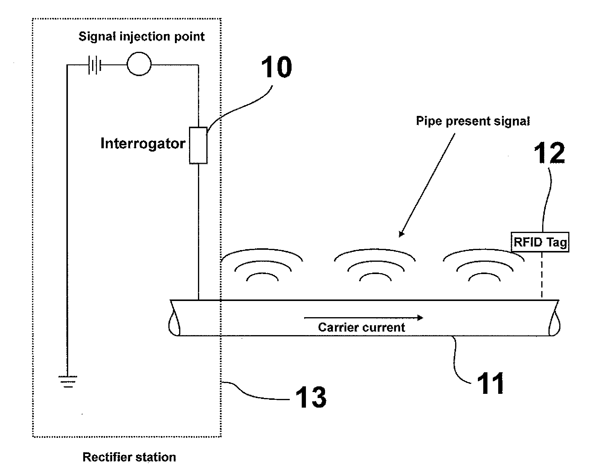
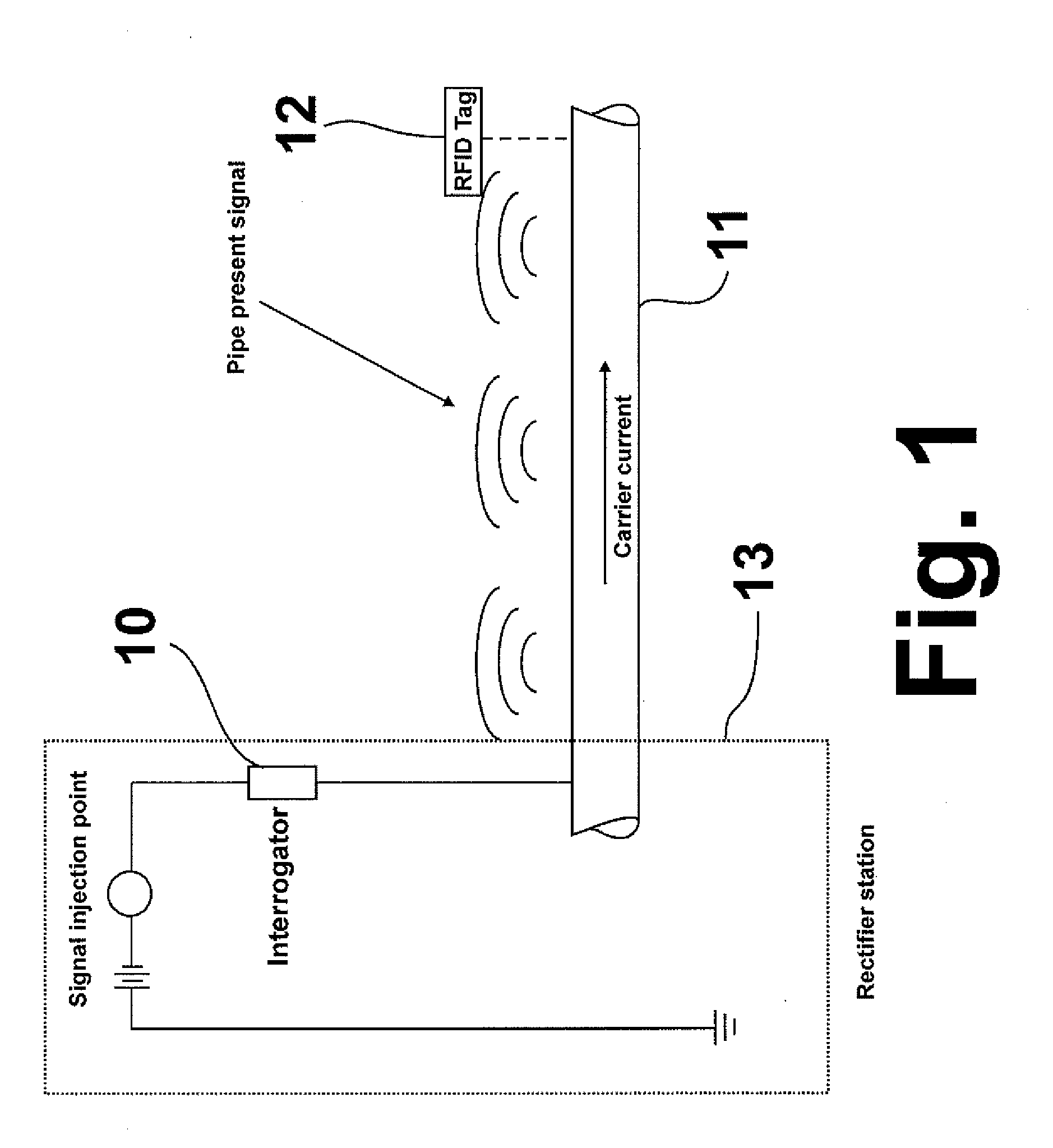
[0023]The fundamental feature of this invention is the use of a pipeline or, in the case of plastic pipes, a tracer wire, as a backbone for a communication system that networks sensors to monitor the pipeline. This invention features the use of a network of continuously active sensors buried along a right-of-way, a communication network method to collect the sensor data, a continuously present locating signal on the pipeline or tracer wire, continuous monitoring of the pipeline or tracer wire impedance to detect damage, and means to correlate sensor data including, but not limited to, impedance, impact, and pipe potential, all of which contribute to reducing the risk of excavation damage to pipelines. It is to be understood that the terms “pipeline” and “pipe”, which are used interchangeably herein, are made of electrically conductive materials or, in the case of electrically non-conductive pipes, such as plastic pipe, are provided with some form of electrical conductivity means, su...


PUM


Abstract

A method for underground pipeline monitoring in which a continuous alternating electrical current having a current frequency in a range of about 1 kHZ to about 8 kHz is imparted onto a pipeline, producing an alternating magnetic field at the current frequency along the pipeline. Distributed along the pipeline is a network of RFID tag sensors which absorb an amount of energy from the alternating magnetic field. The impedance of the sensors is modulated, producing a modulated sensor impedance which is detected at a location proximate the location at which the continuous alternating electrical current is imparted onto the pipeline.

Description

BACKGROUND OF THE INVENTION[0001]The U.S. Government has a paid-up license in this invention and the right in limited circumstances to require the patent owner to license others on reasonable terms as provided for by the terms of Grant No. DTPH56-09-G-PHPD01 awarded by the U.S. Department of Transportation.FIELD OF THE INVENTION[0002]This invention relates to a method and system for monitoring underground pipelines. In one aspect, this invention relates to a communication method and system utilizing underground pipelines as conduits for transmission of data and other information relating to pipeline condition and status. In one aspect, this invention relates to the use of radio frequency identification (RFID) coils for communication of data and other information along an underground pipeline. In yet another aspect, this invention relates to the use of sensors to track pipeline properties.DESCRIPTION OF RELATED ART[0003]Underground pipelines are widely used to transport a variety of ...

Claims


Application Information

Patent Timeline
IPC IPC(8): G01R27/28
CPCG01V15/00F17D5/00F17D5/005F17D3/01F17D5/06F17D1/08
Inventor ZIOLKOWSKI, CHRISTOPHER JOHNHUEBLER, JAMES EMERSONMENSINGER, JR., MICHAEL CHRISTIAN
Owner GAS TECH INST
Why Eureka
Try Eureka