Hockey Goalie Stick

a hockey and goalie technology, applied in the field of hockey goals, can solve the problems of difficult to machine into intricate shapes, heavy hard wood, and difficult to achieve the effect of relative eas

Inactive Publication Date: 2013-02-21
STEFAN ALAN D
View PDF3 Cites 21 Cited by
  • Summary
  • Abstract
  • Description
  • Claims
  • Application Information

AI Technical Summary

Benefits of technology

[0009]The present invention uses composite materials to construct a surface feature on the face of the paddle. The purpose of the surface feature is to change the angle of reflection of the puck, so that it no longer equals the angle of incidence of the shot, when it strikes the face of the paddle. Ideally, the surface fea

Problems solved by technology

Unfortunately, due to current designs, and current constructions, and the placement of the goalie stick, this is often times impossible.
However, these hard

Method used


Image

  • Hockey Goalie Stick
  • Hockey Goalie Stick
  • Hockey Goalie Stick

Examples


Embodiment Construction

[0017]The following description represents the inventor's current preferred embodiment. The description is not meant to limit the invention, but rather to illustrate its general principles of operation and construction. Examples are illustrated with the accompanying drawings.

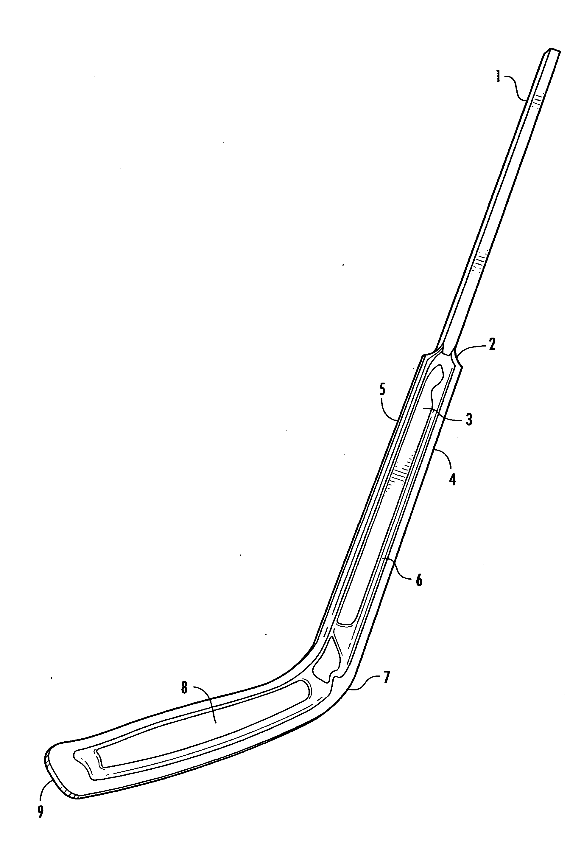
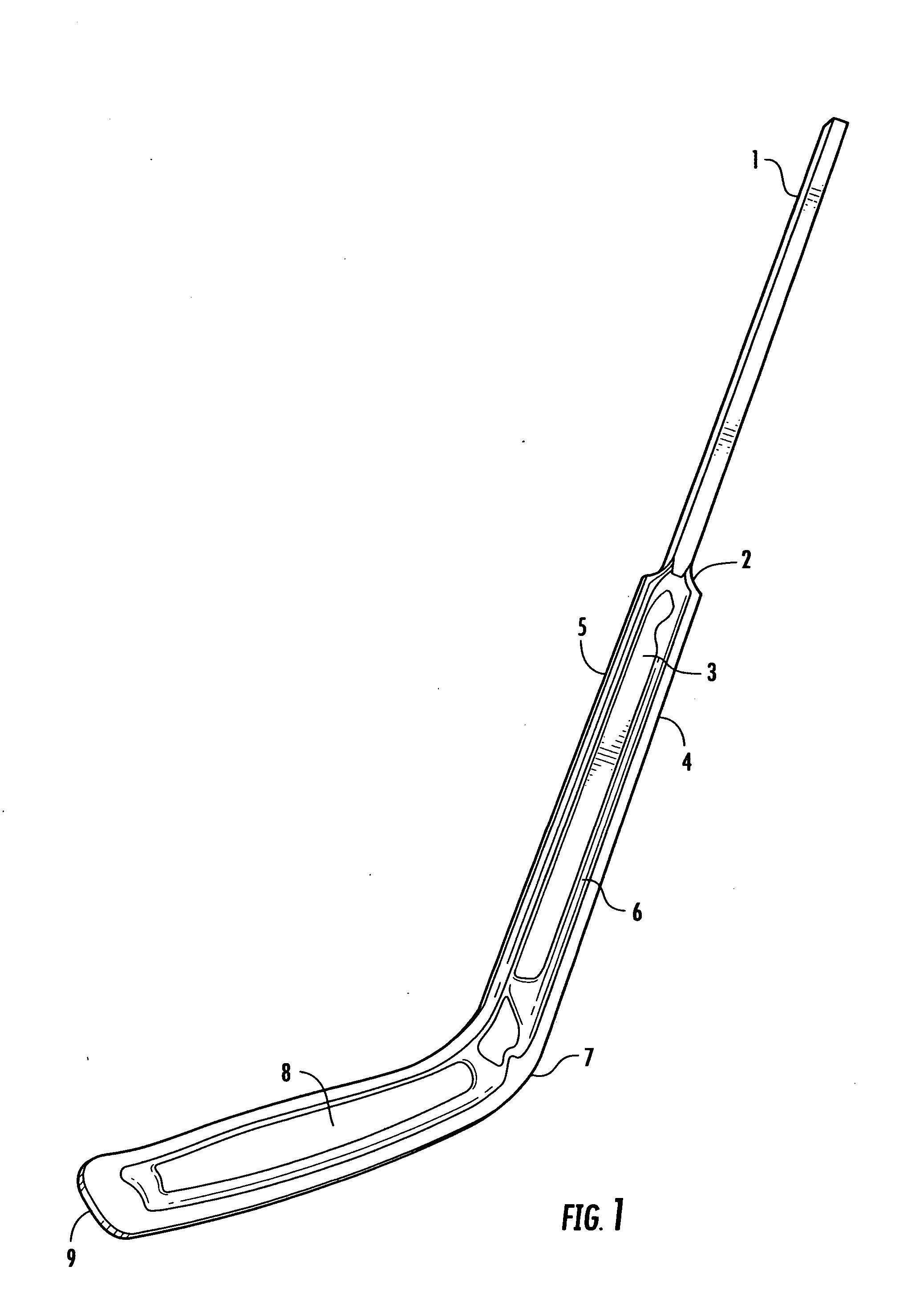
[0018]FIG. 1 shows the front view of the preferred embodiment, with a full right-handed blade. The stick is comprised of a shaft 1, a paddle 3, and a blade 8. The shaft 1 is joined to the paddle 3 at a transition point 2. The blade 8 has a toe-end 9 and a heel-end 7. The blade 8 joins with the paddle 3 near the heel end 7 of the blade 8. The same holds true of the right-handed blade 8 version in FIG. 3.

[0019]In the preferred embodiment in FIG. 1, the paddle 3 has a surface feature 6, which runs the length of the paddle 3. In FIG. 5, a cross-sectional view of the surface feature 6 can be seen. In this drawing, the surface feature 6 is semi-circular, with a near-constant cross-section. The surface feature 6 extend...


PUM


Abstract

A hockey goalie stick comprising a blade, a paddle, and a shaft, wherein the face of the paddle has one or more surface features. The surface feature(s) on the face of the paddle are designed to change the angle of a rebounding puck, thus allowing the goalie to more easily keep the puck away from the opposing team.

Description

FIELD OF INVENTION[0001]This invention relates to the field of sporting equipment, specifically, hockey sticks.BACKGROUND OF INVENTION[0002]Hockey is a fast moving sport, requiring players to master a number of skills, simultaneously, such as skating and stick handling. Goalies, in particular, have to master a number of skills. They have to skate, perform blocking motions with their body and legs, and use their hands and stick to catch or block the puck. Hockey is a game of speed, and the goalie is expected to keep the puck from going into the net by any means necessary. When shots are fired on net, it is extremely important for a goalie to be able to minimize the number of rebounds, and / or be able to redirect the puck to an area away from the front of the net.[0003]When blocking the puck, most goalies would like to control the angle or direction of the rebound. Unfortunately, due to current designs, and current constructions, and the placement of the goalie stick, this is often tim...

Claims


Application Information

Patent Timeline
IPC IPC(8): A63B59/14
CPCA63B59/0077A63B2209/02A63B59/14A63B59/70A63B60/48A63B2102/24A63B60/00
Inventor STEFAN, ALAN D.
Owner STEFAN ALAN D
Why Eureka
Try Eureka