Control device for hybrid vehicle

a control device and hybrid technology, applied in the direction of machines/engines, electric control, vehicle sub-unit features, etc., can solve the problems of inability to appropriately suppress phenomena, inability to properly reduce engine speed, and likely to occur vibration in vehicles due to passing through the rotation speed region, so as to reduce engine speed, reduce engine speed, and reduce engine speed

Active Publication Date: 2021-02-04
TOYOTA JIDOSHA KK
View PDF0 Cites 1 Cited by
  • Summary
  • Abstract
  • Description
  • Claims
  • Application Information

AI Technical Summary

Benefits of technology

[0014]According to the aspect of the disclosure, since the output torque of the rotating machine at the time of decreasing the engine speed of the engine is made larger as the turbocharging pressure increases, it is possible to reduce the engine speed of the engine more appropriately during the transition to stop the engine in turbocharging.
[0015]Further, according to the aspect of the disclosure, at the time of decreasing the engine speed of the engine, the output torque of the rotating machine is controlled based on the feedback control amount of the feedback control that controls the output torque of the rotating machine such that the engine speed of the engine becomes the target engine speed gradually reducing toward zero, and the feedforward control amount of the output torque of the rotating machine that is made larger when the turbocharging pressure is higher than when the turbocharging pressure is lower. In this way, it is possible to appropriately control the output torque of the rotating machine at the time of decreasing the engine speed of the engine.
[0016]Further, according to the aspect of the disclosure, the feedback gain in the feedback control is corrected by learning control based on the deviation between the value of the stop transition time at the current control and the target value to make the value of the stop transition time when the engine is stopped at the next control close to the target value. In this way, it is possible to appropriately reduce the engine speed of the engine such that the stop transition time becomes the target value.
[0017]Further, according to the aspect of the disclosure, the feedforward control amount is corrected by learning control based on the deviation between the value of the stop transition time at the current control and the target value to make the value of the stop transition time when the engine is stopped at the next control close to the target value. In this way, it is possible to appropriately reduce the engine speed of the engine such that the stop transition time becomes the target value.
[0018]Further, according to the aspect of the disclosure, the turbocharging pressure when the engine is being brought to a stop is estimated based on a detection value obtained by a sensor that detects the turbocharging pressure obtained at a starting time point of a control for stopping the engine and an elapsed time from the starting time point of the control for stopping the engine. In this way, for example, even when the value detected by the sensor cannot be used in a low turbocharging pressure range due to the decrease in sensor accuracy, it is possible to control the output torque of the rotating machine at the time of decreasing the engine speed of the engine according to the turbocharging pressure.
[0019]Further, according to the aspect of the disclosure, in the hybrid vehicle including the engine with the turbocharger and the differential mechanism that splits power of the engine to transmit the power to drive wheels and the rotating machine, it is possible to appropriately suppress vibration generated in the vehicle when the engine is being brought to a stop.

Problems solved by technology

In this case, since the losses of pumps of the engine differ due to the remaining turbocharging pressure, the engine speed of the engine cannot be properly reduced with the uniformly controlled output torque of the rotating machine.
Therefore, there is a possibility that vibration generated in vehicle due to passing through the rotation speed region where the resonance phenomenon is likely to occur cannot be appropriately suppressed.

Method used


Image

  • Control device for hybrid vehicle
  • Control device for hybrid vehicle
  • Control device for hybrid vehicle

Examples


first embodiment

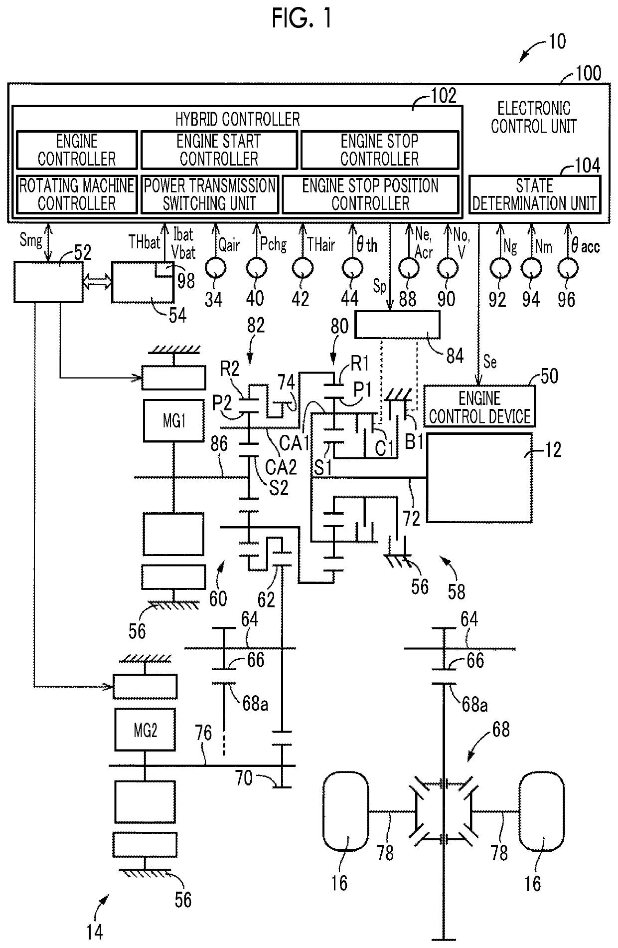
[0102]In the embodiment, a vehicle 200 as illustrated in FIG. 12, which is different from the vehicle 10 described in the first embodiment, is illustrated. FIG. 12 is a diagram illustrating a schematic configuration of a vehicle 200 to which the disclosure is applied. In FIG. 12, the vehicle 200 is a hybrid vehicle including an engine 202, a first rotating machine MG1, a second rotating machine MG2, a power transmission device 204, and drive wheels 206.

[0103]The engine 202, the first rotating machine MG1, and the second rotating machine MG2 make the same configuration as the engine 12, the first rotating machine MG1, and the second rotating machine MG2 described in the first embodiment. In the engine 202, the engine torque Te is controlled by controlling an engine control device 208, such as an electronic throttle valve, a fuel injection device, an ignition device, and a wastegate valve provided in the vehicle 200, by an electronic control unit 240 to be described later. Each of the...

second embodiment

[0126]Further, in the above-described second embodiment, the stepped transmission unit 218 is exemplified as the automatic transmission that forms a part of the power transmission path between the differential mechanism 230 and the drive wheels 206, but the present disclosure is not limited to this mode. The automatic transmission may be, for example, a synchronous meshing parallel two-shaft type automatic transmission, a well-known dual clutch transmission (DCT) that is the synchronous meshing parallel two-shaft type automatic transmission and has two systems of input shafts, and a well-known belt-type continuously variable transmission.

third embodiment

[0127]Further, in the above-described third embodiment, in the vehicle 300, the engine 302 is not mechanically connected to the drive wheels 310, but is not limited to this mode. For example, in the vehicle 300, the engine 302 and the drive wheels 310 are connected through a clutch. For example, the clutch may be engaged during high-speed traveling to mechanically transmit the power of the engine 302 to the drive wheels 310. Further, the power transmission device 308 may include an automatic transmission.

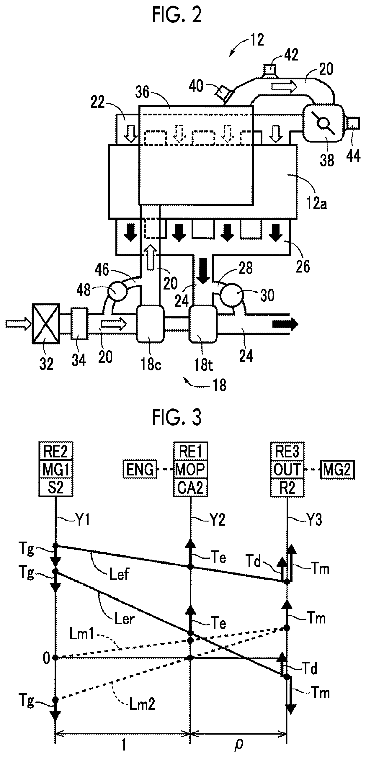
[0128]Further, in the above-described embodiments, a mechanical pump type turbocharger that is driven to rotate by an engine or an electric motor may be provided in addition to or instead of the exhaust turbine type turbocharger 18. Alternatively, the turbocharger 18 may include an actuator capable of controlling the rotation speed of the compressor 18c, for example, an electric motor.

[0129]It should be noted that the above description is merely an embodiment, and that the present d...


PUM


Abstract

An MG1 torque at a time of decreasing an engine speed of an engine is made larger when a turbocharging pressure by a turbocharger is higher than when the turbocharging pressure is lower. In this way, even if the losses of pumps of the engine differ due to the remaining turbocharging pressure during a transition of stopping the engine in turbocharging, it is possible to appropriately reduce the engine speed. Therefore, when the engine is being brought to a stop, it is possible to appropriately suppress vibration generated in the vehicle.

Description

CROSS-REFERENCE TO RELATED APPLICATION[0001]This application claims priority to Japanese Patent Application No. 2019-139242 filed on Jul. 29, 2019, incorporated herein by reference in its entirety.BACKGROUND1. Technical Field[0002]The disclosure relates to a control device for a hybrid vehicle including an engine with a turbocharger and a rotating machine.2. Description of Related Art[0003]A control device for a hybrid vehicle is well known which includes an engine and a rotating machine capable of adjusting the engine speed of the engine. For example, the above vehicle is disclosed in Japanese Unexamined Patent Application Publication No. 10-306739 (JP 10-306739 A). In JP 10-306739 A, it is disclosed that, when a signal for stopping the operation of an engine is output, the fuel injection to the engine is stopped and the output torque of a rotating machine is controlled such that the engine speed of the engine is reduced faster than a natural change to quickly pass through a rotati...

Claims


Application Information

Patent Timeline
Patent Type & Authority Applications(United States)
IPC IPC(8): B60W20/15B60K6/24B60K6/36F02B37/12
CPCB60W20/15B60K6/24B60K6/36F02B37/12F02D2041/1436B60W2710/083B60Y2200/92B60Y2400/435B60W2510/0633B60W2710/0644B60W30/20B60W20/00B60W10/08B60W10/06B60K6/445B60W2030/206Y02T10/72F02D41/0007F02D29/02B60K6/365B60K6/387B60K2006/381B60K6/547B60W20/40B60W2510/0671B60W2050/0012B60W2050/0014B60W2050/0088B60W2510/0638B60W2050/0039B60W20/11Y02T10/12Y02T10/62
Inventor TABATA, ATSUSHIOKUDA, KOICHIMATSUBARA, TOORUHIASA, YASUHIROTSUCHIDA, YASUTAKA
Owner TOYOTA JIDOSHA KK
Why Eureka
Try Eureka