Eureka AIR delivers breakthrough ideas for toughest innovation challenges, trusted by R&D personnel around the world.

Spark ignition-type internal combustion engine

a technology of internal combustion engine and spark ignition, which is applied in the direction of combustion engine, valve arrangement, electrical control, etc., can solve the problems of extreme deterioration of driving comfort, increase engine output, and reduce heat loss , the effect of increasing the boost pressur

Active Publication Date: 2012-12-13
TOYOTA JIDOSHA KK
View PDF11 Cites 3 Cited by
  • Summary
  • Abstract
  • Description
  • Claims
  • Application Information

AI Technical Summary

Benefits of technology

[0006]Accordingly, an object of the present invention is to provide a spark ignition-type internal combustion engine wherein a first mechanical compression ratio control and a second mechanical compression ratio control are alternatively carried out, the first mechanical compression ratio control makes the mechanical compression ratio in the low engine load side operation area higher than that in the high engine load side operation area to increase the expansion ratio in the low engine load side operation area, the second mechanical ratio control makes the expansion ratio in the low engine load side operation area lower than that in the low engine load side operation area made by the first mechanical compression ratio control and a boost pressure control increases the boost pressure like a step change when the engine load becomes a set engine load in the low engine load side operation area or over, which can restrain deterioration of drivability when the second mechanical compression ratio control is carried out.
[0011]When the first mechanical compression ratio control is carried out, if the engine load becomes the set engine load or higher, the boost pressure is increased like a step change to satisfactorily increase the engine output. On the other hand, for example, when the second mechanical compression ratio control is carried out to warm up the catalytic device, because the expansion ratio in the low engine load side operation area is lower than that in the low engine load side operation area made by the first mechanical compression ratio control to make the heat efficiency low, the engine operation area to realize the low fuel consumption shifts to the low engine speed and high engine load side. Accordingly, it is preferable to decrease the engine speed and to increase the engine load by using the transmission, such that the engine output is maintained. Therefore, if the set engine load in the boost pressure control is maintained, the frequency of operating in about the set engine load is increased so that the engine load frequently becomes higher or lower than the set engine load and thus the drivability extremely deteriorates because increasing and decreasing the boost pressure is repeated like a step change. However, according to the spark ignition-type internal combustion engine as set forth in claim 1 of the present invention, the set engine load in the boost pressure control when the second mechanical compression ratio control is carried out is made higher than that when the first mechanical compression ratio control is carried out so that even if by using the transmission the engine speed is decreased and the engine load is increased such that the engine output is maintained, the engine load does not frequently become higher or lower than the set engine load and thus the deterioration of the drivability caused by the change of the boost pressure can be restrained.
[0012]According to the spark ignition-type internal combustion engine as set forth in claim 2 of the present invention, in the spark ignition-type internal combustion engine as set forth in claim 1, when the engine load becomes the set engine load or higher, the boost pressure control makes an engine driven-type or electrically driven-type supercharger in a non-operating state operate to increase the boost pressure like a step change. Therefore, the boost pressure can be easily increased like a step change.
[0013]According to the spark ignition-type internal combustion engine as set forth in claim 3 of the present invention, in the spark ignition-type internal combustion engine as set forth in claim 1, when the engine load becomes the set engine load or higher, the boost pressure control makes an opening degree of a waste gate valve small to increase the boost pressure like a step change by a turbocharger. Therefore, the boost pressure can be easily increased like a step change.
[0014]According to the spark ignition-type internal combustion engine as set forth in claim 4 of the present invention, in the spark ignition-type internal combustion engine as set forth in claim 1, when the engine load becomes the set engine load or higher, the boost pressure control makes an angle of variable nozzles of a variable nozzle-type turbocharger change to increase the boost pressure like a step change by the variable nozzle-type turbocharger. Therefore, the boost pressure can be easily increased like a step change

Problems solved by technology

However, in this way, if the heat efficiency in the low engine load side operation area is made low, the engine operation area to realize the low fuel consumption shifts to the low engine speed and high engine load side.
Therefore the engine load frequently becomes higher or lower than the set engine load and thus drivability extremely deteriorates because increasing and decreasing the boost pressure is repeated like a step change.

Method used


Image

  • Spark ignition-type internal combustion engine
  • Spark ignition-type internal combustion engine
  • Spark ignition-type internal combustion engine

Examples


Embodiment Construction

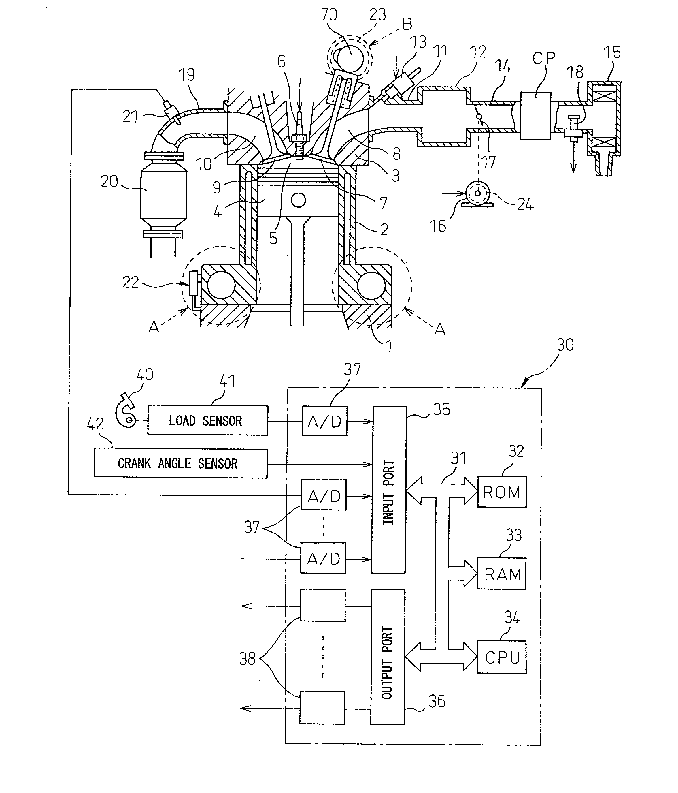
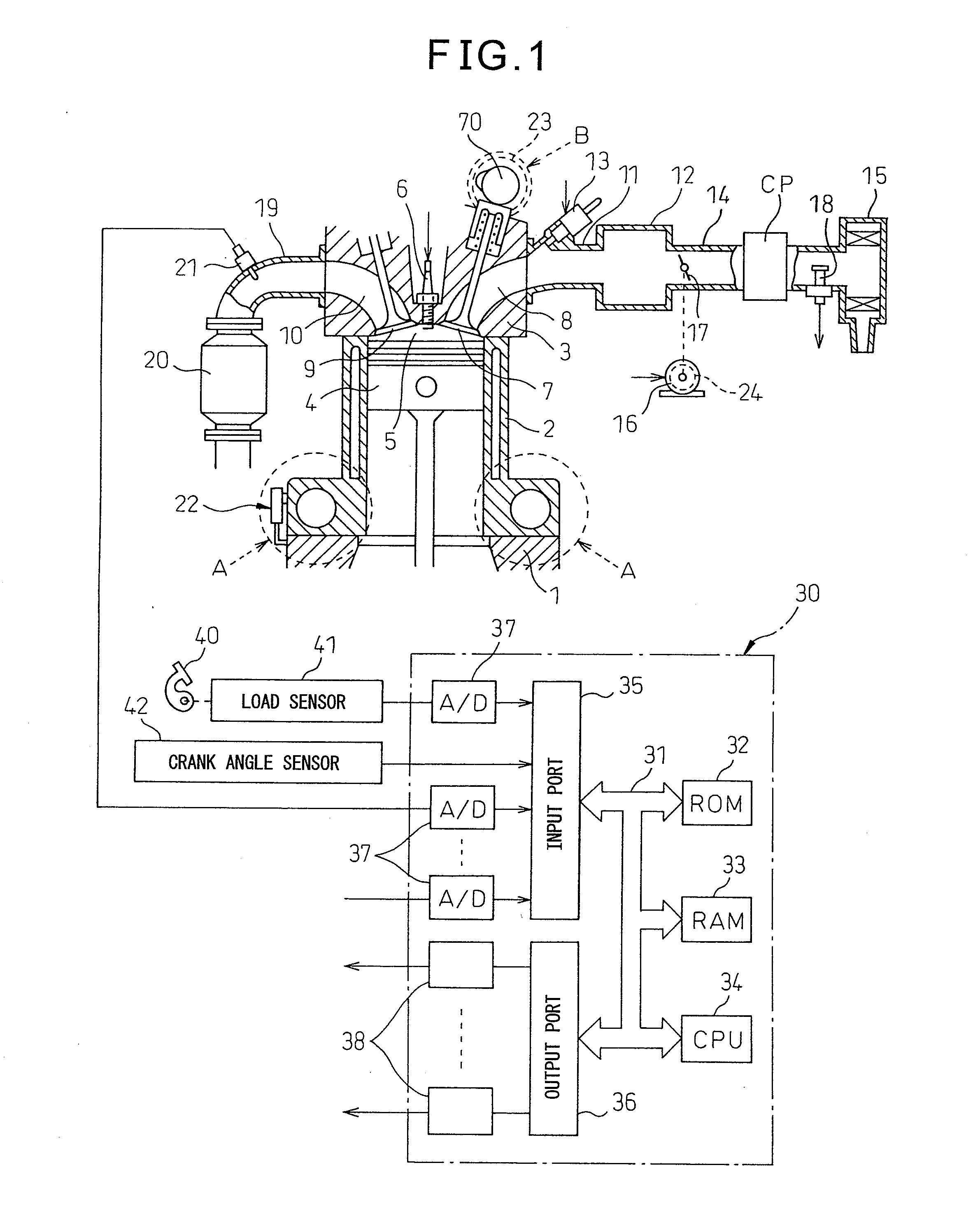
[0029]FIG. 1 is a side cross-sectional view of a spark ignition-type internal combustion engine according to the present invention. Referring to FIG. 1, 1 indicates a crank case, 2 a cylinder block, 3 a cylinder head, 4 a piston, 5 a combustion chamber, 6 a spark plug arranged at the top center of the combustion chamber 5, 7 an intake valve, 8 an intake port, 9 an exhaust valve, and 10 an exhaust port. The intake port 8 is connected through an intake branch tube 11 to a surge tank 12, while each intake branch tube 11 is provided with a fuel injector 13 for injecting fuel toward a corresponding intake port 8. Note that each fuel injector 13 may be arranged at each combustion chamber 5 instead of being attached to each intake branch tube 11.

[0030]The surge tank 12 is connected through an intake duct 14 to an air cleaner 15, and the intake duct 14 is provided inside it with a throttle valve 17 driven by an actuator 16 and an intake air amount detector 18 using for example a hot wire. O...


PUM


Abstract

A spark ignition-type internal combustion wherein a first mechanical compression ratio control and a second mechanical compression ratio control are alternatively carried out, the first mechanical compression ratio control makes the mechanical compression ratio in the low engine load side operation area higher than that in the high engine load side operation area to increase the expansion ratio in the low engine load side operation area, the second mechanical ratio control makes the expansion ratio in the low engine load side operation area lower than that in the low engine load side operation area made by the first mechanical compression ratio control and a boost pressure control increases the boost pressure like a step change when the engine load becomes a set engine load in the low engine load side operation area or higher, is provided. The set engine load of the boost pressure control when the second mechanical compression ratio control is carried out is set higher than that when the first mechanical compression ratio control is carried out.

Description

TECHNICAL FIELD[0001]The present invention relates to a spark ignition-type internal combustion engine.BACKGROUND ART[0002]In a spark ignition-type internal combustion engine, generally, the lower the engine load is, the worse the heat efficiency becomes. Therefore, it has been proposed that the mechanical compression ratio in the low engine load side operation area is increased by a variable compression ratio mechanism higher than that in the high engine load side operation area, to increase the expansion ratio and thereby improve the heat efficiency (refer to Japanese Unexamined Patent Publication Nos. 2007-303423, 2005-067591, 2006-283601, and 2002-038961).[0003]In such a spark ignition-type internal combustion engine with a variable compression ratio mechanism, even when in the low engine load side operation area the engine load is a set engine load or over, it is preferable to increase the engine output by supercharging. For this purpose, when the engine load reaches the set en...

Claims


Application Information

Patent Timeline
Patent Type & Authority Applications(United States)
IPC IPC(8): F02D15/00F02B37/22
CPCF02D13/0238F02D13/0269F02D15/04F02B75/041F01L2001/34496F02B37/18F02B37/22Y02T10/142F01L1/3442F02D41/0007F02D41/062F02D2041/001Y02T10/12
Inventor AKIHISA, DAISUKE
Owner TOYOTA JIDOSHA KK
Why Eureka
Eureka Blog
Learn More