Method of operating a material handling machine

a technology of material handling machine and operating method, which is applied in the field of method of operating a material handling machine, can solve the problems of engine lugging down, significant slowdown, and high load to be applied to the engine, and achieve the effect of automatic increase of engine speed and fuel saving

Active Publication Date: 2015-07-16
J C BAMFORD EXCAVATORS LTD
View PDF3 Cites 2 Cited by
  • Summary
  • Abstract
  • Description
  • Claims
  • Application Information

AI Technical Summary

Benefits of technology

[0011]c) unactuating the control means so as to simultaneously stop movement of said at least one of the stabilisers and allow the engine speed to reduce towards the first engine speed.
[0012]Advantageously as the or each stabiliser is moved then the engine speed is automatically increased without the need of operator input. Once the or each stabiliser has been moved to an appropriate position (e.g. either deployed or retracted) then the engine speed will reduce, thereby saving fuel.

Problems solved by technology

Certain scenarios may cause the engine to lug down (i.e. slow down significantly below a normal idle speed) or even stall.
Because the engine has not properly had time to warm up, and because the hydraulic oil is cold, the full deployment of the stabilisers causes a high load to be applied to the engine, which as mentioned above, may be running at an idle speed.
This high load may be sufficient for the engine to “lug” down, i.e. slow down significantly below a normal idle speed, or may even cause the engine to stall.
Clearly this is inconvenient for the operator since it causes delays.

Method used


Image

  • Method of operating a material handling machine
  • Method of operating a material handling machine
  • Method of operating a material handling machine

Examples


example 1

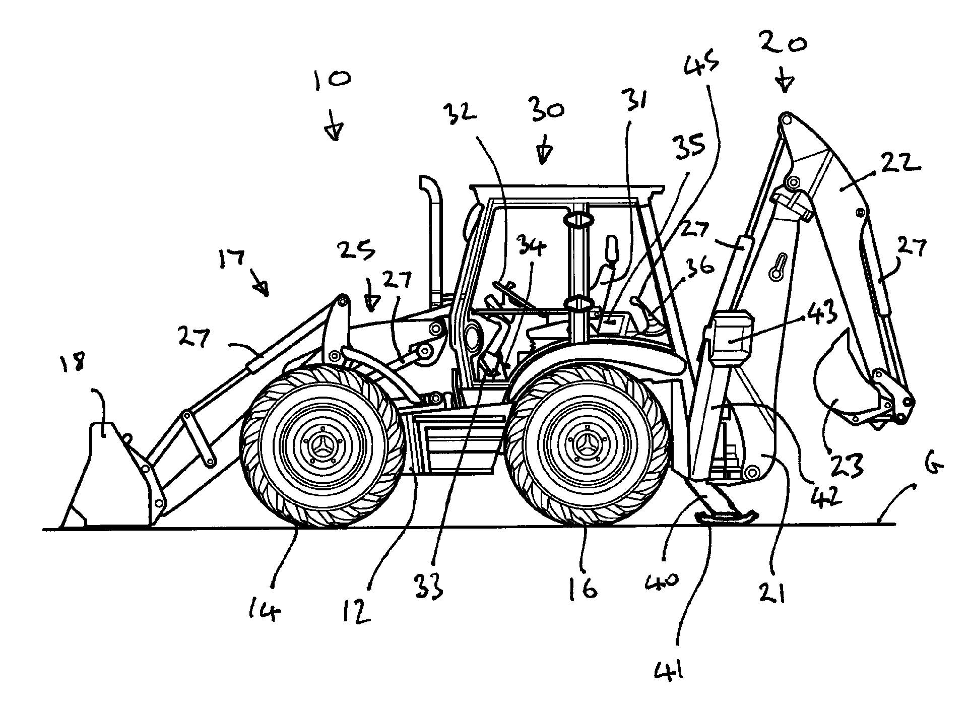
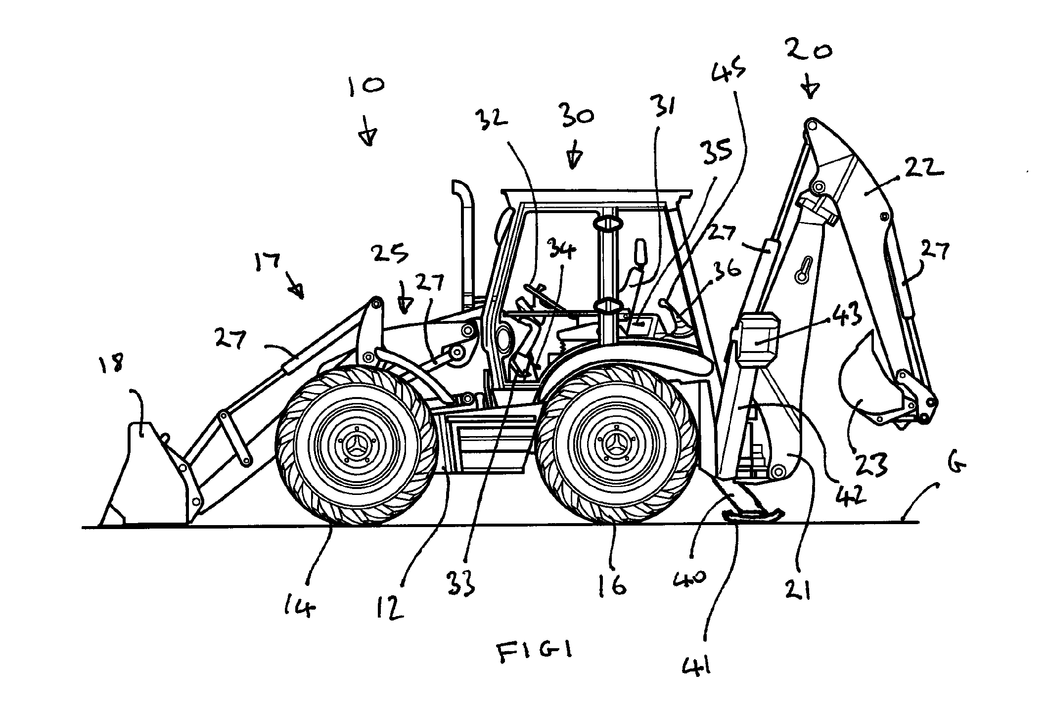
[0043]The vehicle is driven to a site and parked ready for working the following day. The shovel 18 has been lowered into engagement with the ground and the rear right and rear left stabilisers are in their retracted position such that the ground engaging feet 41 and 43 are remote from the ground.

[0044]The next day the operator enters the cab and starts the engine. The engine will be running at an idle speed, in this example 800 rpm. The operator then turns the seat 31 to face rearwardly and operates the control device 45 so as to move the rear right stabiliser 40 and rear left stabiliser 42 into their deployed positions such that the ground engaging foot 41 and ground engaging foot 43 engage the ground. The control device 45 operates to both deploy the stabilisers and also to increase the engine speed to a working speed, in this example 1200 rpm. This increase in speed of the engine provides more power to drive the hydraulic pump which in turn can produce more flow to the hydraulic...

example 2

[0047]At the end of a working day wherein the operator has been digging a trench with a back hoe loader using the back hoe, the operator parks the vehicle with the stabilisers 40 and 42 in a deployed position.

[0048]At the next working day, the operator enters the cab and starts the engine which then runs at an idle speed. The operator wishes to continue digging the trench but now needs to move the vehicle forwards, perhaps the length of the vehicle so as to continue digging the trench. In order to do this the operator therefore turns the seat to face rearwardly and operates the control device 45 to move both stabilisers 40 and 42 from the deployed position to the retracted position. Control device 45 causes the engine speed to increase from idle to 1200 rpm which results in the rear stabilisers moving more quickly to the retracted position and also prevents lug down or stall of the engine. Once the stabilisers have reached their retracted position, the operator releases the control ...


PUM


Abstract

A method of operating a material handling machine, the machine including an engine, ground engaging means, and a control means selectively operable by an operator to move the ground engaging means, the method including the steps of:
    • a) starting with the ground engaging means in a first position and the engine running at a first engine speed,
    • b) actuating the control means to move the ground engaging means towards a second position, actuation of the control means causing the engine speed to increase,
    • c) unactuating the control means so as to simultaneously stop movement of the ground engaging means and allow the engine speed to reduce towards the first engine speed.

Description

BACKGROUND OF THE INVENTION[0001]The present invention relates to a method of operating a materials handling machine.[0002]Known materials handling machines such as back hoe loaders or mini excavators can perform material handling operations whilst stationary. Thus, the back hoe of a back hoe loader can be used to move material whilst the back hoe loader is stationary. Similarly, the working arm of a mini excavator can be used to move material while the excavator is stationary.[0003]Such machines include stabilisers or the like which can be moved into engagement with the ground to help stabilise the machine whilst performing material handling operations. In one example the back hoe loader has a stabiliser on each side of the back of the machine. Each stabiliser can be individually lowered into contact with the ground. It is often advantageous to lower the stabilisers into engagement with the ground such that the rear wheels of the back hoe loader are lifted from the ground. This pro...

Claims


Application Information

Patent Timeline
Patent Type & Authority Applications(United States)
IPC IPC(8): E02F9/22E02F9/08E02F9/20
CPCE02F9/2246E02F9/085E02F9/2066F02D29/04E02F9/2058
Inventor MCKEE, MICHAELCOOK, MATT
Owner J C BAMFORD EXCAVATORS LTD
Why Eureka
Try Eureka