Pneumatic tire with improved crown durability

a pneumatic tire and crown technology, applied in the field of pneumatic tires, can solve the problems of reducing the durability of belt edge durability and crown durability, the tire is prone to significant heat buildup in the crown area, and the pneumatic tire is used in severe service applications of heavy vehicles that operate at slow speeds, so as to achieve the same overall tire weight and improve the durability and stiffness of the crown

Inactive Publication Date: 2013-02-28
THE GOODYEAR TIRE & RUBBER CO
View PDF4 Cites 2 Cited by
  • Summary
  • Abstract
  • Description
  • Claims
  • Application Information

AI Technical Summary

Benefits of technology

[0008]The invention is directed to pneumatic tires for heavy vehicle service that include a carcass, a tread disposed radially outward of the carcass, a sidewall intersecting the tread at a shoulder, and a belt reinforcing structure positioned radially between the carcass and the tread. The belt reinforcing structure includes four belt layers, each layer reinforced by parallel cords the four belts characterized by their cord orientation and angles. A first radially inner belt layer, an adjacent second belt layer overlaying the first belt layer and a third belt layer overlaying the second belt layer are all oriented directionally extending right (R) relative to an equatorial center plane of the tire, a fourth radially outer belt layer overlaying the third belt layer has cords directionally extending left (L). The pneumatic tires of the invention containing these belt layers have improved crown durability and stiffness while maintaining the same overall tire weight.DEFINITIONS

Problems solved by technology

Pneumatic tires for severe service applications on heavy vehicles that operate at slow speeds, such as refuse trucks, construction trucks, buses and tankers, are prone to significant heat buildup in the tire crown area.
The heat buildup reduces both belt edge durability and crown durability.
In service applications like commercial bus tires, not only is the crown region subject to high temperatures, but also the bead area adjacent the hot brakes become overheated during use.
Tires under exposure to heavy loads and constant stops for braking such as buses and waste haulers see extremely high service temperatures.
These high temperatures reduce the life of the tires.
This is only feasible if the tire is made sufficiently strong for its required service application.
A cool running, but inferior strength tire casing is not a workable solution.
It is this dilemma that is most difficult and challenging to solve when designing tires for these heavy loaded commercial vehicles such as waste haulers and buses.

Method used


Image

  • Pneumatic tire with improved crown durability
  • Pneumatic tire with improved crown durability
  • Pneumatic tire with improved crown durability

Examples


Embodiment Construction

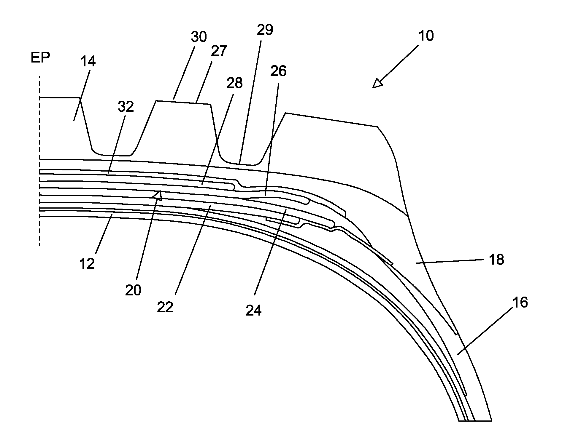
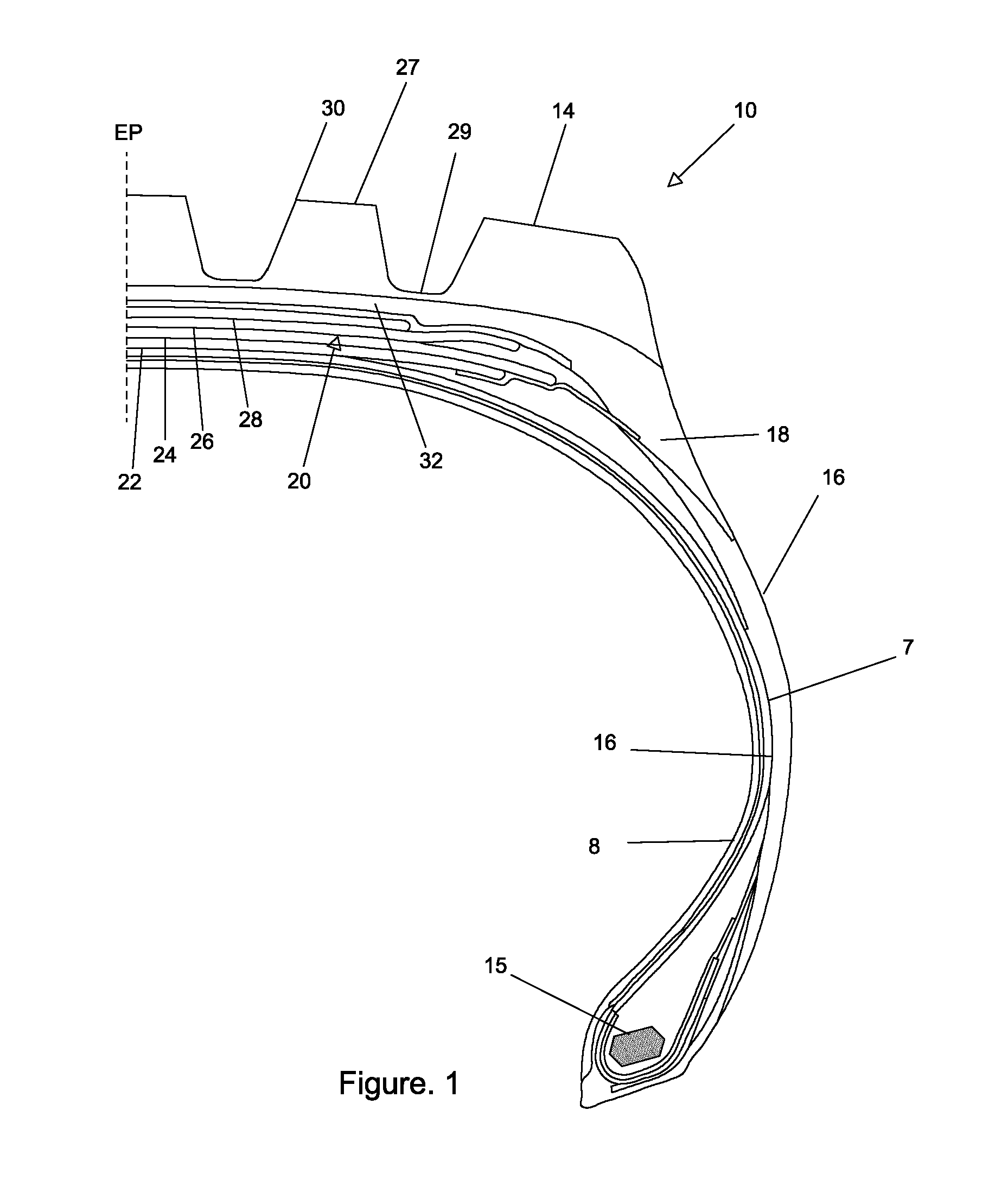
[0033]With reference to the FIGS. 1 and 3, a pneumatic tire 10 includes a carcass 12, a ground-engaging tread 14, a sidewall 16, and a shoulder 18 defined at the juncture between the sidewall 16 and the tread 14. The tread 14 has a ground contacting surface 27 separated by grooves 29. When mounted on a vehicle, the tread 14 furnishes traction and tire 10 contains a fluid that supports the vehicle load. The tire carcass 12 has one or more carcass plies 7 extending from the bead 15 under the belt structure 20 to the opposite bead 15. Radially inward of the at least one ply 7 is an air impervious inner liner 8. Pneumatic tire 10 is understood to have mirror symmetry for reflection about an equatorial plane EP bisecting tire 10 so that the following description is understood to apply to the full tire width. Pneumatic tire 10 has a footprint (FP), as described hereinabove.

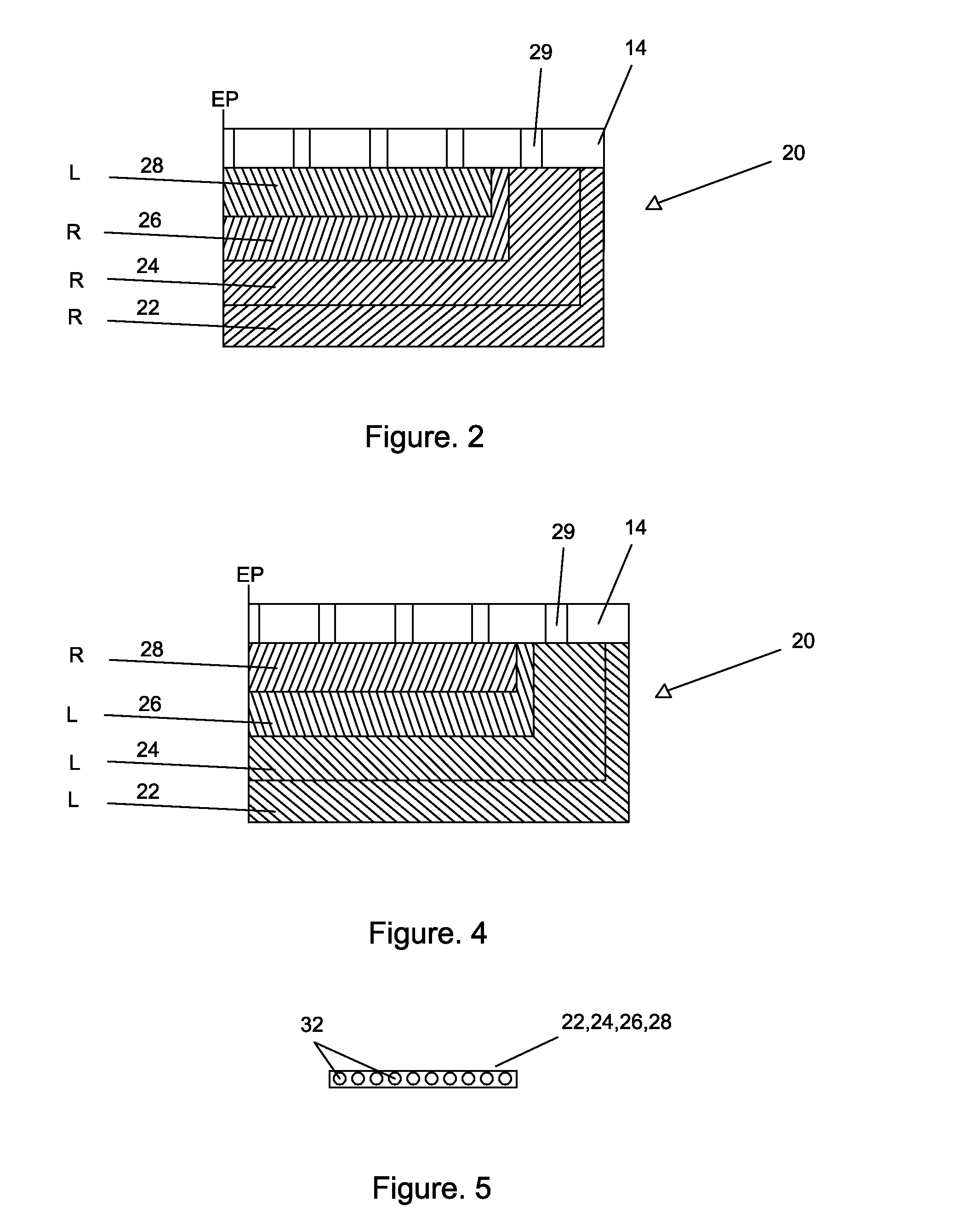
[0034]Arranged radially between the carcass 12 and the tread 14 is a belt package 20, generally indicated by referenc...


PUM

PropertyMeasurementUnit
cord angleaaaaaaaaaa
angleaaaaaaaaaa
angleaaaaaaaaaa

Abstract

The invention is directed to pneumatic tires for heavy vehicle service that include a carcass, a tread disposed radially outward of the carcass, a sidewall intersecting the tread at a shoulder, and a belt reinforcing structure positioned radially between the carcass and the tread. The belt reinforcing structure includes four belt layers, each layer reinforced by parallel cords the four belts characterized by their cord orientation and angles. A first radially inner belt layer, an adjacent second belt layer overlaying the first belt layer and a third belt layer overlaying the second belt layer are all oriented directionally extending right (R) relative to an equatorial center plane of the tire, a fourth radially outer belt layer overlaying the third belt layer has cords directionally extending left (L). The pneumatic tires of the invention containing these belt layers have improved crown durability and stiffness while maintaining the same overall tire weight.

Description

TECHNICAL FIELD[0001]The present invention generally relates to pneumatic tires and, more specifically, to pneumatic tires for use on large commercial vehicles.BACKGROUND OF THE INVENTION[0002]Pneumatic tires for severe service applications on heavy vehicles that operate at slow speeds, such as refuse trucks, construction trucks, buses and tankers, are prone to significant heat buildup in the tire crown area. The heat buildup reduces both belt edge durability and crown durability. Conventional pneumatic tires incorporate a belt package that includes multiple cut belt layers wrapped about the circumference of the tire. Typically, the cut belt layers in conventional pneumatic tires for use on such heavy vehicles are formed from a single type of belt wire and are narrower in width than the tire footprint. Conventionally, the width of the widest cut belt layer is less than 90% of the tire footprint. The belt layers are most typically stacked in layers with the cords being oriented equal...

Claims


Application Information

Patent Timeline
Patent Type & Authority Applications(United States)
IPC IPC(8): B60C9/18
CPCB60C2009/2016B60C9/18B60C2009/2019B60C9/2006B60C2200/06Y10T152/10765B60C9/20B60C2009/2012Y10T152/10792Y10T152/10801B60C9/28
Inventor KOTANIDES, JR., JOHN
Owner THE GOODYEAR TIRE & RUBBER CO
Why Eureka
Try Eureka