
Electronic vital-sign monitoring system

a vitalsign monitoring and electronic technology, applied in the field of electronic vitalsign monitoring systems, can solve the problems of irregular heart rate status, can be considered abnormal, and general electronic vitalsign monitoring devices cannot monitor their heart status regularly

Active Publication Date: 2013-02-28
CHANG KUO YUAN
View PDF8 Cites 4 Cited by
  • Summary
  • Abstract
  • Description
  • Claims
  • Application Information

AI Technical Summary

Benefits of technology

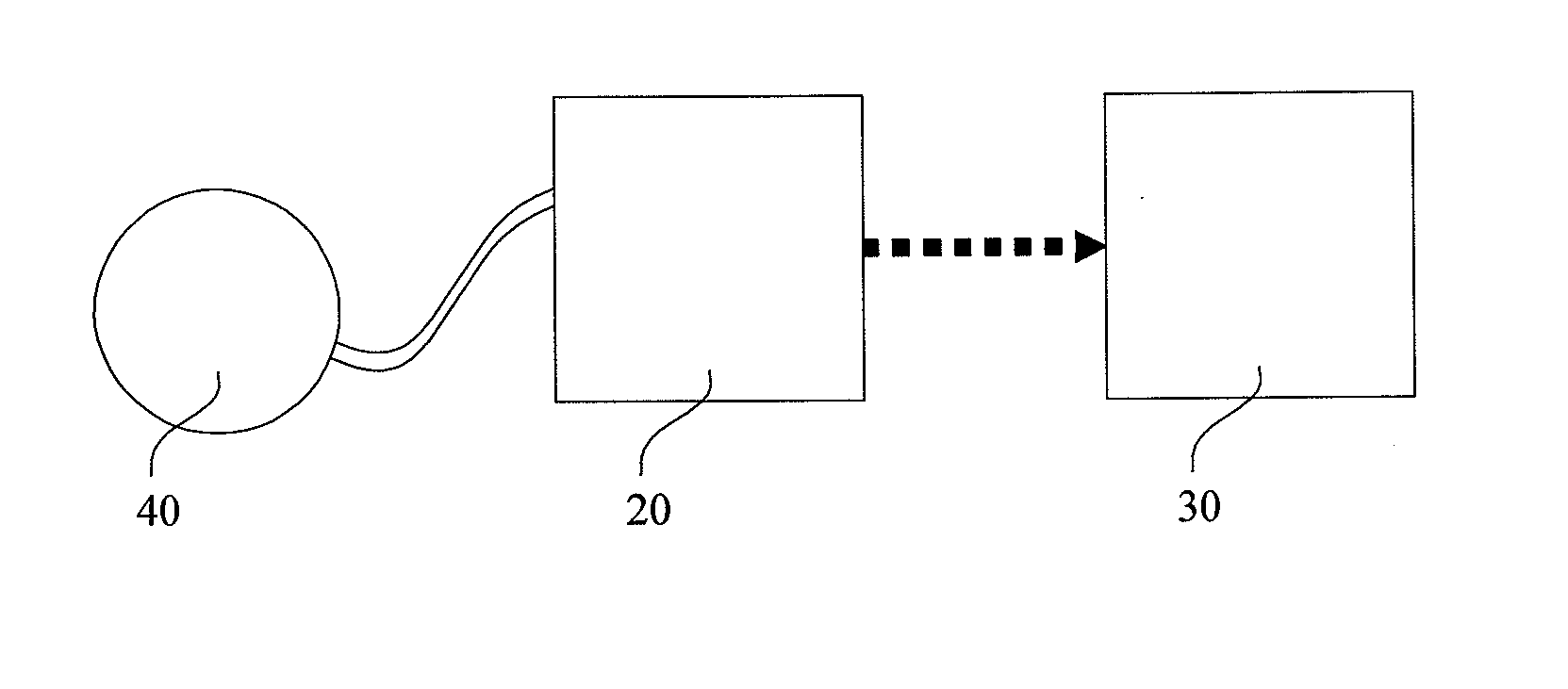
The present invention is a patent for an electronic system that can monitor important vital signs, such as heart rate and blood pressure. The device has detection functions and can also detect heart frequency spectrum. It offers telecare services to patients, elders, and general users, providing proper assistance based on their requirements. The system has a detection unit, a processing unit, and a transfer unit for transferring the detected data to a database, either locally or through the cloud. Additionally, the invention includes an electronic device that can connect to an external electronic device for further analysis and sharing of data. Overall, the invention improves monitoring capabilities and provides advanced assistance to users.

Problems solved by technology

If there are several disorder frequency waveforms beside the main frequency waveforms, it means the heart rate status appears irregular and can be considered abnormal.
For elders or patients who need special health care in the community, general electronic vital-sign monitoring devices cannot regularly monitor their heart status.
Since general electronic vital-sign devices cannot detect heart frequency spectrum, users who desire to know heart status must go to major hospitals or medical center for precise examination and physician diagnose, which is very inconvenient especially for patients with mobility problems.

Method used


Image

  • Electronic vital-sign monitoring system
  • Electronic vital-sign monitoring system
  • Electronic vital-sign monitoring system

Examples


Embodiment Construction

[0017]The detailed description is provided below and the preferred embodiments described are only for the purpose of description rather than for limiting the present invention.

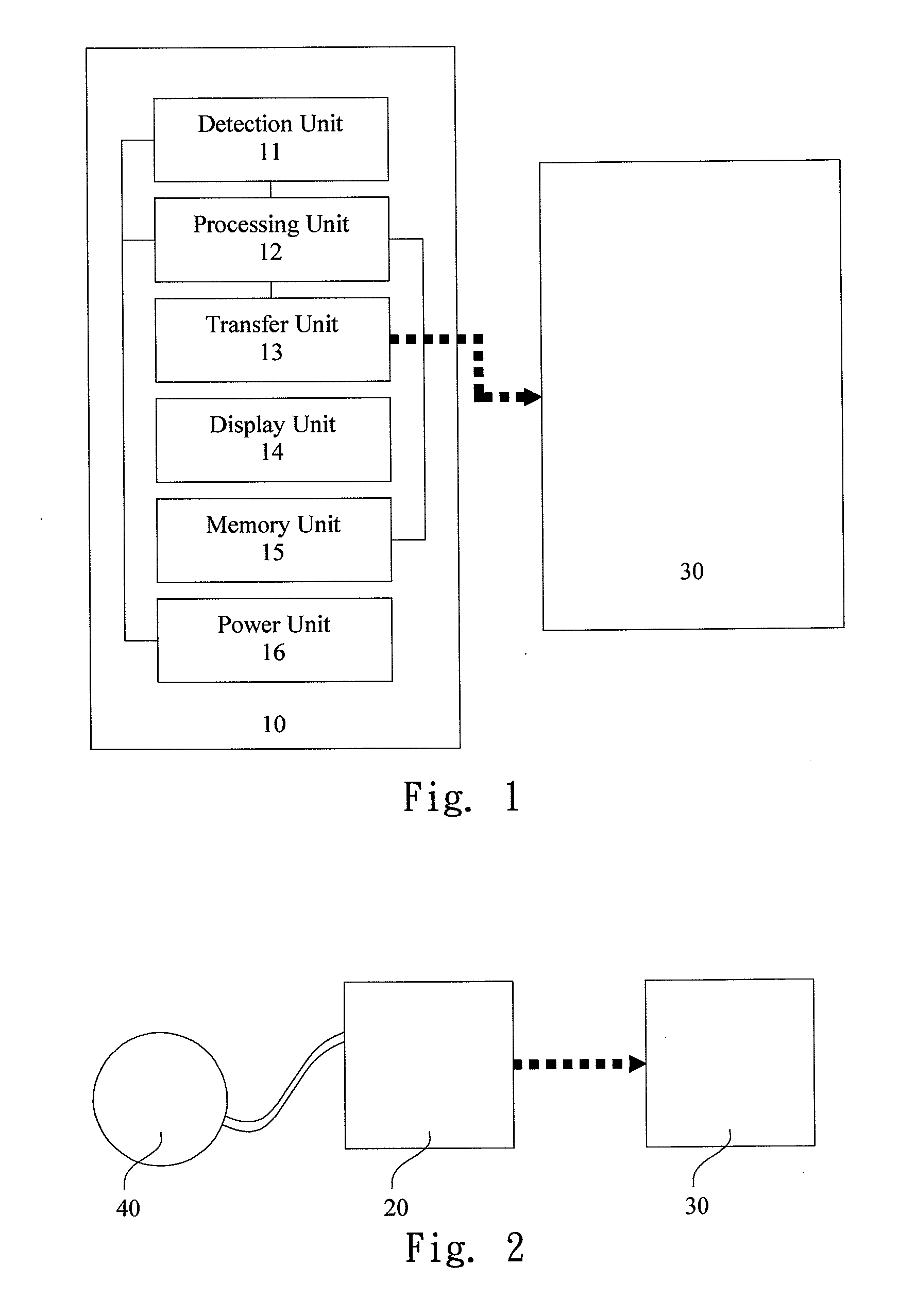
[0018]FIG. 1 is a block diagram schematically illustrating the structure of the electronic vital-sign monitoring system according to one embodiment of the present invention. As shown in the figure, an electronic vital-sign monitoring system 10 comprises a detection unit 11, for detecting a physiological value; a processing unit 12, connected to the detection unit 11, for computing the physiological value and obtaining a heart frequency spectrum; and a transfer unit 13, electrically connected to the processing unit 12, for transferring the physiological value and the heart frequency spectrum to a database 30.

[0019]Continue the above description, as shown in FIG. 1, the electronic vital-sign monitoring system 10 further comprises a display unit 14, a memory unit 15 and a power unit 16, wherein the display unit 1...


PUM


Abstract

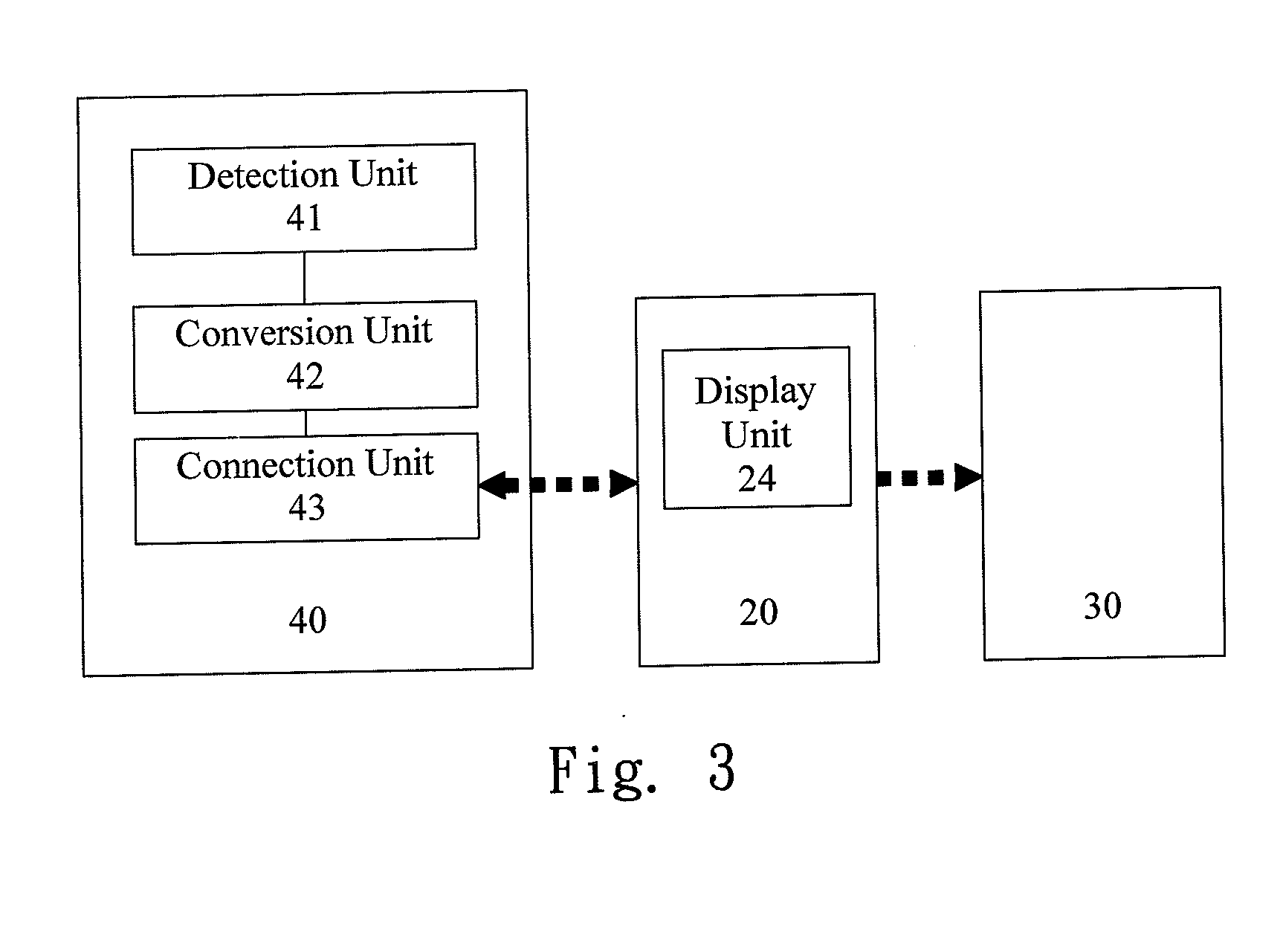
A electronic vital-sign monitoring system is provided here, which uses an external electronic device to compute a physiological value detected by an electronic vital-sign monitoring device and obtain a heart frequency spectrum; and provide power to the electronic vital-sign monitoring system; and further transfer the computed physiological value and the heart frequency spectrum to a database for data integration and incident reporting. In addition to the original function of detecting physiological values, the electronic vital-sign monitoring system further can detect heart frequency spectrum and offers telecare service to help patients, elders and general users according to different requirements.

Description

BACKGROUND OF THE INVENTION [0001]1. Field of the Invention[0002]The present invention relates to an electronic vital-sign monitoring system, and more particularly to a multifunctional vital-sign monitoring system with a database such as blood pressure & heart frequency spectrum monitor, blood oxygen & heart frequency spectrum monitor, electrocardiogram & heart frequency spectrum monitor or patient monitor for monitoring heart frequency spectrum.[0003]2. Description of the Prior Art[0004]In recent years, population ageing and low birth rate have gradually become a trend. Therefore, designing and implementing for the elder community (retirement community) is a significant target for community development. Regarding to health care in the community for elders, not only portable electronic are necessary to detect physiological values such as blood pressure, heart rate etc., but a more completed telecare system is required to monitor users' health status. By using medical instruments of ...

Claims


Application Information

Patent Timeline
Patent Type & Authority Applications(United States)
IPC IPC(8): A61B5/0255
CPCA61B5/0022A61B5/0255G16H40/67
Inventor CHANG, KUO-YUAN
Owner CHANG KUO YUAN
Learn More