[0012]The disclosure, including the accompanying drawings, is illustrated by way of example and not by way of limitation. It should be noted that references to “an” or “one” embodiment in this disclosure are not necessarily to the same embodiment, and such references mean at least one.
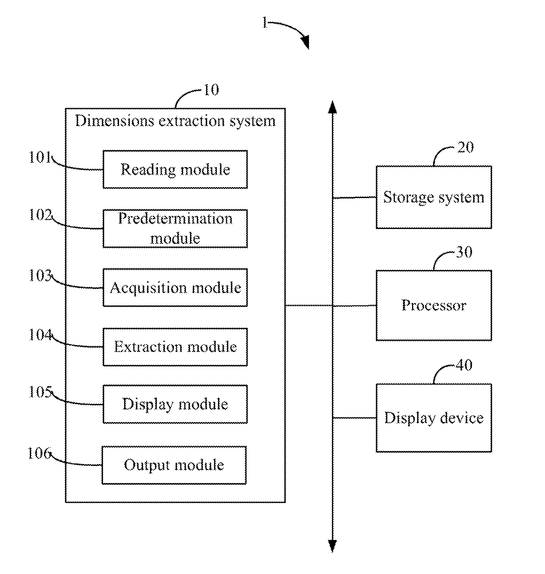
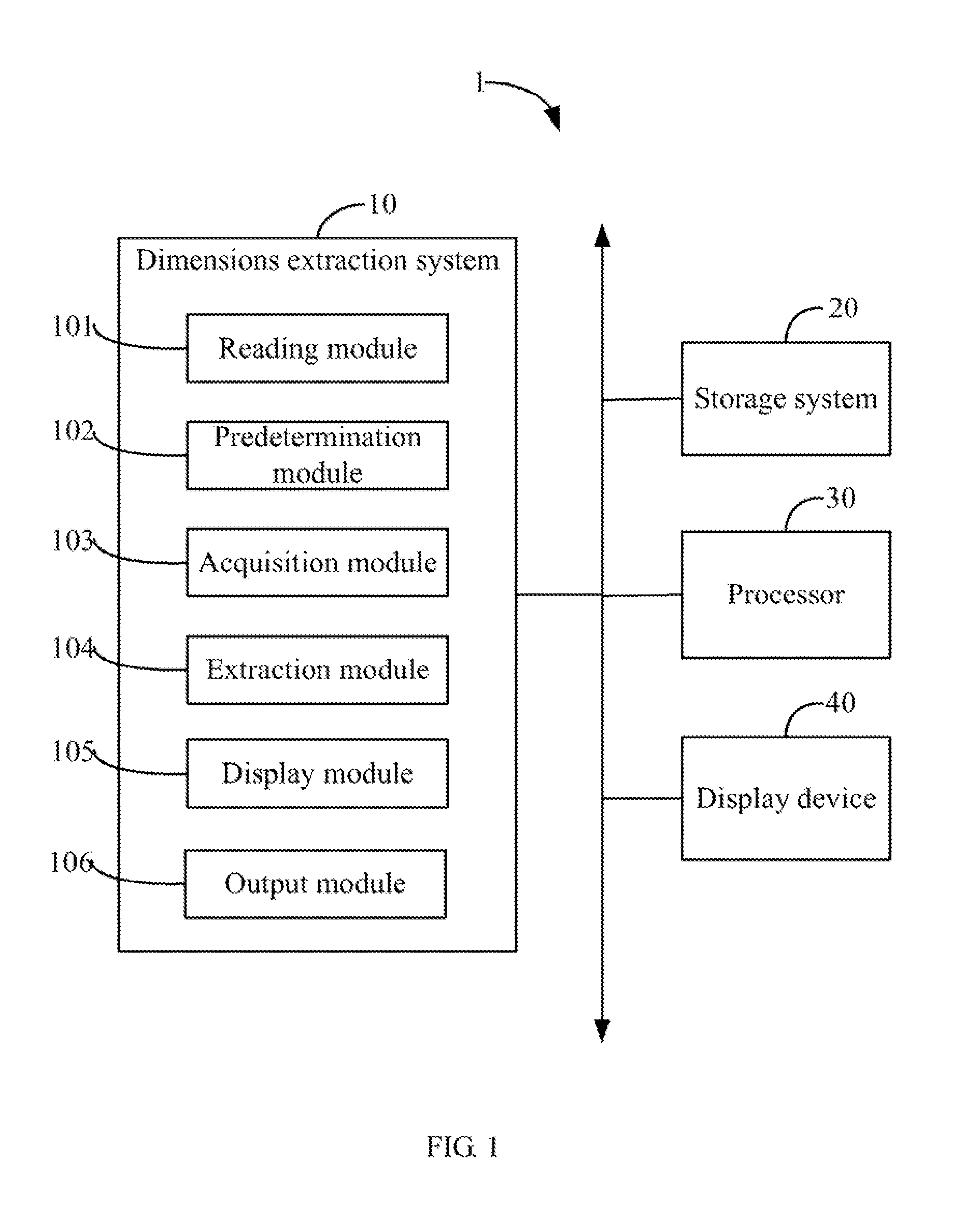
[0013]In general, the word “module”, as used herein, refers to logic embodied in hardware or firmware, or to a collection of software instructions, written in a programming language, such as, Java, C, or assembly. One or more software instructions in the modules may be embedded in firmware, such as in an EPROM. The modules described herein may be implemented as either software and/or hardware modules and may be stored in any type of non-transitory computer-readable storage medium or other storage device. Some non-limiting examples of non-transitory computer-readable storage medium include CDs, DVDs, BLU-RAY, flash memory, and hard disk drives.
[0014]FIG. 1 is a block diagram of one embodiment of a computing device 1 including a dimensions extraction system 10. In the embodiment, the computing device 1 further includes a storage system 20, at least one processor 30, and a display device 40. The storage system 20 stores at least one engineering drawing 50 of a product, such as a computer aided design engineering drawing as shown in FIG. 2. The dimensions extraction system 10 may be in form of one or more programs that are stored in the storage system 20 and executed by the at least one processor 30. FIG. 1 is just one example of the computing device 1 that can be included with more or fewer components than shown in other embodiments, or have a different configuration of the various components. The engineering drawing 50 may include multiple layers where each layer may include different information about the product.
[0015]In one embodiment, the storage system 20 may be a random access memory (RAM) for temporary storage of information, and/or a read only memory (ROM) for permanent storage of information. In other embodiments, the storage system 20 may also be an external storage device, such as a hard disk, a storage card or a data storage medium. The at least one processor 30 executes computerized operations of the computing device 1 and other applications to provide functions of the computing device 1.
[0016]In one embodiment, the dimensions extraction system 10 may include a reading module 101, a predetermination module 102, an acquisition module 103, an extraction module 104, a display module 105, and an output module 106. The modules 101-106 may comprise a plurality of functional modules each comprising one or more programs or computerized codes that are stored in the storage system 20, and can be accessed and executed by the at least one processor 30.
[0017]FIG. 3 is a flowchart of one embodiment of a method for extracting dimensions of a product using the computing device 1 of FIG. 1. Depending on the embodiment, additional steps may be added, others removed, and the ordering of the steps may be changed.
[0018]In step S1, the reading module 101 reads an engineering drawing 50 of the product from the storage system 20. The engineering drawing 50 may include a plurality of measurement elements, such as points, lines, or circles. The engineering drawing 50 further includes several unique identifiers and dimensions corresponding to the identifiers. Each of the identifiers corresponds to one or more measurement elements of the product. If one or more measurement elements have the same identifier, having the same identifier signifies that the one or more measurement elements have the same dimensions, such as the same shape, or width or length. In one embodiment, a dimension corresponding to the identifier indicates a theoretical value of the one or more measurement elements that have the identifier. In other embodiments, the dimension may further indicate an upper tolerance and a lower tolerance of the theoretical value, and a number of the one or more measurement elements which have that identifier.
[0019]Referring to FIG. 2, for example, a dimension “2×240±0.15” corresponding to an identifier “{circle around (1)}” indicates that the theoretical value is 240, that both the upper tolerance and the lower tolerance are 0.15, and that the number of measurement elements which have that identifier “{circle around (1)}” is two. For another example, a dimension 206.13 corresponding to an identifier “{circle around (2)}” indicates that the theoretical value is 206.13 and the number is one by default, but the dimension 206.13 does not indicate an upper tolerance or a lower tolerance.
[0020]In step S2, the predetermination module 102 further predetermines a group of tolerances of theoretical values of the dimensions. If a dimension does not indicate an upper tolerance and a lower tolerance of a theoretical value of a dimension, the upper tolerance and the lower tolerance of the theoretical value can be determined according to the predetermined tolerances. For example, referring to FIG. 4, if a theoretical value is in a range from zero to six, an upper tolerance and a lower tolerance of the theoretical value are both determined as 0.05, and if a theoretical value is in a range from seven to thirty, an upper tolerance and a lower tolerance of the theoretical value are both determined as 0.1.
[0021]In step S3, the acquisition module 103 acquires a first layer of the engineering drawing 50 that includes all identifiers, and a second layer of the engineering drawing 50 that includes all dimensions. Usually, the engineering drawing 50 includes properties of each identifier and each dimension drawn in the engineering drawing 50. The properties may indicate a color, a line type, a line style, a layer, and a plot style of each identifier and each dimension, for example. The properties of an identifier or a dimension in the engineering drawing 50 indicate a layer where the identifier or the dimension is drawn. The acquisition module 103 can select an identifier and a dimension randomly, and acquire the first layer and the second layer of the engineering drawing 50 according to the properties of the identifier and the dimension in the engineering drawing 50.
[0022]In step S4, the extraction module 104 extracts all identifiers in the first layer of the engineering drawing 50, and adds the identifiers into an identifier field of a dimension list 60 according to a sequence of the identifiers, as shown in FIG. 5. The dimension list 60 may include several fields for recording the identifiers and the dimensions, and the dimension list 60 is stored in the storage system 20.
[0023]The extraction module 104 further extracts a location of each identifier in the engineering drawing 50, and adds the location of each identifier into a location field of the dimension list 60. For example, referring to FIG. 6, if the identifier “{circle around (1)}” is located in an “A” row and “4” column of the engineer drawing 50, the location of the identifier “{circle around (1)}” can be represented as “A4”.
[0024]In step S5, the extraction module 104 further extracts the dimensions corresponding to each identifier in the second layer of the engineer drawing 50, and adds the theoretical values, the upper tolerances, the lower tolerances, and the numbers of measurement elements indicated by each dimension into a dimension field of the dimension list 60, referring to FIG. 5. In the embodiment, if a location of an identifier is closest to a location of a dimension drawn in the engineering drawing 50, the extraction module 104 determines that the dimension corresponds to the identifier. For example, the identifier “{circle around (1)}” is closest to the dimension “2×240±0.15” in FIG. 2. If the dimensions do not indicate the upper tolerances and the lower tolerances, the extraction module 104 determines the upper tolerances and the lower tolerances according to the predetermined tolerances.
[0025]In step S6, the display module 105 displays the dimension list 60 on the display device 40 for allowing a user to check and amend the dimension list 60. The dimension list 60 includes the identifiers, the locations of the identifiers, the theoretical values, the upper tolerances, the lower tolerances, and the number of each type of measurement elements. If the user finds errors, such as duplicate identifiers in the dimension list 60, the user can amend the dimension list 60, and the display module 105 saves the amended dimension list 60 in the storage system 20.
[0026]FIG. 7A shows a user interface for displaying the dimension list 60. The dimension list 60 includes a displaying area 601 and an amendment area 602. When the user selects a group of dimension data in the displaying area 601, such as the dimension data corresponding to the identifier “{circle around (1)}”, the user can amend the group of dimension data in the amendment area 602. The dimension list 60 can be simplified as the amendment area 602 displayed in FIG. 7B.
[0027]In step S7, the output module 106 inserts content of the dimension list 60 into a report file stored in the storage system 20 and displays the report file on the display device 60. The report file may be an EXCEL file, for example.
[0028]Although certain embodiments of the present disclosure have been specifically described, the present disclosure is not to be construed as being limited thereto. Various changes or modifications may be made to the present disclosure without departing from the scope and spirit of the present disclosure.