Wire protection member

a technology of protection member and wire, which is applied in the direction of insulated conductors, inorganic insulators, cables, etc., can solve the problems of increasing the amount of nonwoven material that is required to form the wire protection member, sliding contact with a neighboring, and abrasion, so as to reduce the amount of nonwoven material usage, and increase the reach distance to the wire

Inactive Publication Date: 2013-03-07
SUMITOMO WIRING SYST LTD
View PDF11 Cites 9 Cited by
  • Summary
  • Abstract
  • Description
  • Claims
  • Application Information

AI Technical Summary

Benefits of technology

[0014]With the wire protection member according to the first aspect, the plurality of protruding portions is provided so as to project outward from the outer circumferential portion of the main body portion that covers the outer circumferential portion of the wire. Thus, while the wire protection member can be made of a smaller amount of material when compared to cases where the thickness throughout the wire protection member is increased, a large distance from the outer circumferential-side end portion of the wire protection member to the wire that is covered by the wire protection member, that is, a large reaching distance to the wire can be secured. In this manner, it is possible to obtain high protection performance while suppressing the amount of usage of the nonwoven material.
[0015]With the wire protection member according to the second aspect, the plurality of protruding portions is provided partially in the circumferential direction or in the extending direction of the wire. That is to say, the plurality of protruding portions is formed in only a portion in the circumferential direction or in the extending direction of the wire that may come into contact with a neighboring member, and thus it is possible to reduce the amount of the nonwoven material that is used even more.
[0016]With the wire protection member according to the third aspect, since the plurality of protruding portions is formed as ridges extending in the circumferential direction of the main body portion, bending deformation of the wire protection member is relatively easy, and the wire can be placed in a manner that follows the shape of a placement area.

Problems solved by technology

A wire protection member such as those described above may come into sliding contact with a neighboring member due to vibration and the like during travel of the vehicle and subject to abrasion, depending on a route in which the wire is installed.
However, the method of increasing the thickness throughout the wire protection member increases the amount of usage of the nonwoven material that is required to form the wire protection member.

Method used


Image

  • Wire protection member
  • Wire protection member
  • Wire protection member

Examples


first embodiment

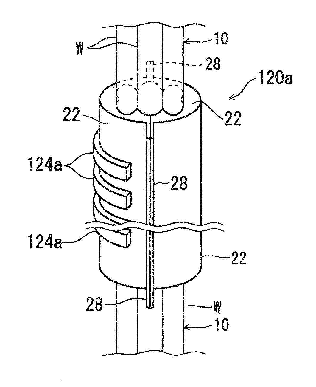
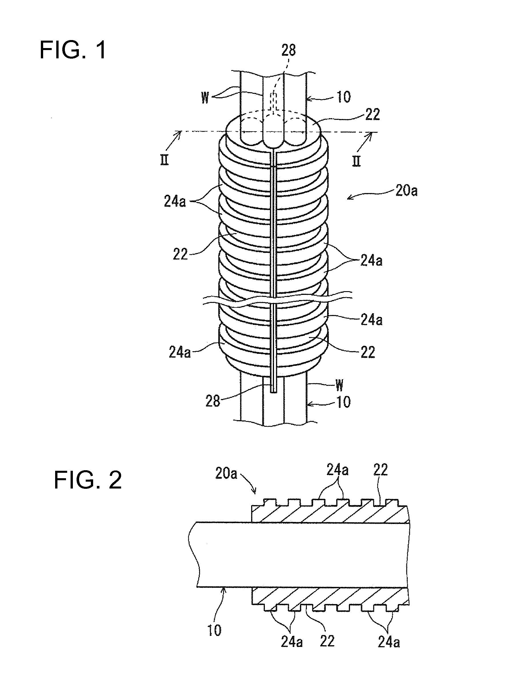
[0032]Hereinafter, a wire protection member 20a will be described (see FIGS. 1 and 2). This wire protection member 20a is formed so as to be able to cover the wire bundle 10. Here, the wire protection member 20a is formed by hot pressing a nonwoven material in a state in which it covers a portion to be protected of the wire bundle 10 in a longitudinal direction. However, it is also possible that the wire protection member 20a covers the entire wire bundle 10 in the longitudinal direction.

[0033]This wire protection member 20a has a main body portion 22 and a plurality of protruding portions 24a.

[0034]The main body portion 22 is a portion that is formed into a shape that covers an outer circumferential portion of the wire bundle 10 (see FIG. 1). Here, the main body portion 22 is formed so as to have an approximately circular outer circumferential shape when viewed in cross section (a plane approximately orthogonal to an extending direction of the wire bundle 10). An inner portion of...

second embodiment

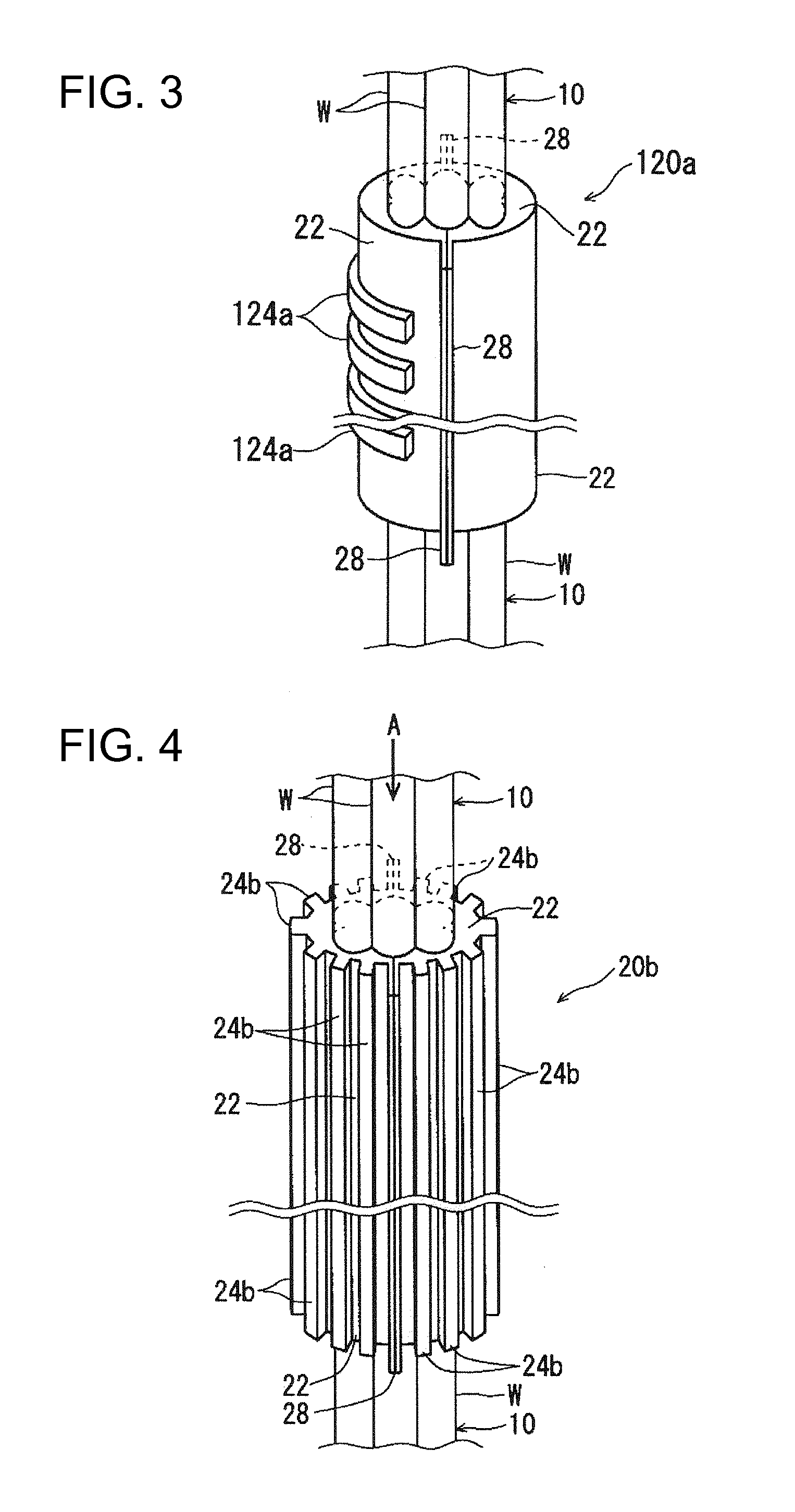
[0052]In the wire protection member 20b the plurality of protruding portions 24b is formed as ridges on the main body portion 22 that extend in the extending direction of the wire bundle 10. That is to say, the wire protection member 20b has a shape composed of a series of alternating recessed and protruding portions in the circumferential direction of the main body portion 22. Here, these protruding portions 24b are provided in positions (other than the positions of the joint end portions 28) equiangularly spaced in the circumferential direction of the main body portion 22. For example, it is preferable that the protruding portions 24b are provided at intervals of 22.5 degrees.

[0053]Moreover, as shown in FIG. 5, each of the plurality of protruding portions 24b is formed into an approximately rectangular shape when viewed in cross section. However, alternatively, each of the plurality of protruding portions 24b may be formed into an approximately triangular shape, an approximately ...

third embodiment

[0058]In the wire protection member 20c the plurality of protruding portions 24c is formed so as to project from the outer circumferential portion of the main body portion 22 as raised dots. More specifically, these protruding portions 24c are provided in positions spaced apart from one another in the outer circumferential portion of the main body portion 22. Here, the protruding portions 24c are provided in positions spaced at approximately regular intervals in a plurality of rows extending in the circumferential direction of the main body portion 22 and in a plurality of columns extending in the extending direction of the wire bundle 10. However, it is also possible that these protruding portions 24c are provided at narrow intervals in an area where higher protection performance is required and at relatively wide intervals in a portion other than this area.

[0059]Moreover, the plurality of protruding portions 24c is formed as approximately cylindrical projections projecting from t...


PUM

PropertyMeasurementUnit
pressureaaaaaaaaaa
thicknessaaaaaaaaaa
bending deformationaaaaaaaaaa

Abstract

Disclosed is a wire protection member that covers and protects a wire. The wire protection member includes a main body portion that is formed by application of heat and pressure to a nonwoven material so as to cover an outer circumferential portion of a wire bundle and a plurality of protruding portions that is formed by application of heat and pressure to a nonwoven material so as to project outward from an outer circumferential portion of the main body portion.

Description

BACKGROUND OF THE INVENTION[0001]1. Field of the Invention[0002]The present invention relates to a technology for protecting wires installed in vehicles and the like.[0003]2. Description of the Related Art[0004]Examples of the technology for protecting wires installed in vehicles include a resin casing (also called “protector”) in which a wire can be inserted and accommodated, a molded wire harness (JP 2008-188958A) produced by molding a sheathing member on an exterior of a wire, and the like.[0005]Moreover, as a technology for protecting a wire, a method has been proposed in which a wire is protected by a wire protection member made of a nonwoven material. More specifically, this wire protection member can be shaped by hot pressing the nonwoven material with the wire being covered by the nonwoven material.[0006]A wire protection member such as those described above may come into sliding contact with a neighboring member due to vibration and the like during travel of the vehicle and...

Claims


Application Information

Patent Timeline
Patent Type & Authority Applications(United States)
IPC IPC(8): H01B3/48
CPCH02G3/0468H02G3/0481
Inventor KAWAI, HIDEKI
Owner SUMITOMO WIRING SYST LTD
Why Eureka
Try Eureka