Manufacturing method of laminated steel and laminated steel manufacturing apparatus

A manufacturing method and a manufacturing device technology, which are applied in lamination devices, electromechanical devices, magnetic core manufacturing, etc., can solve problems such as low productivity, achieve good flatness, shorten the time required for curing, and are not prone to stress concentration Effect

Active Publication Date: 2019-01-25
HONDA MOTOR CO LTD +1
View PDF6 Cites 4 Cited by
  • Summary
  • Abstract
  • Description
  • Claims
  • Application Information

AI Technical Summary

Problems solved by technology

Therefore, there is a problem that productivity becomes low

Method used


Image

  • Manufacturing method of laminated steel and laminated steel manufacturing apparatus
  • Manufacturing method of laminated steel and laminated steel manufacturing apparatus
  • Manufacturing method of laminated steel and laminated steel manufacturing apparatus

Examples


Embodiment 1

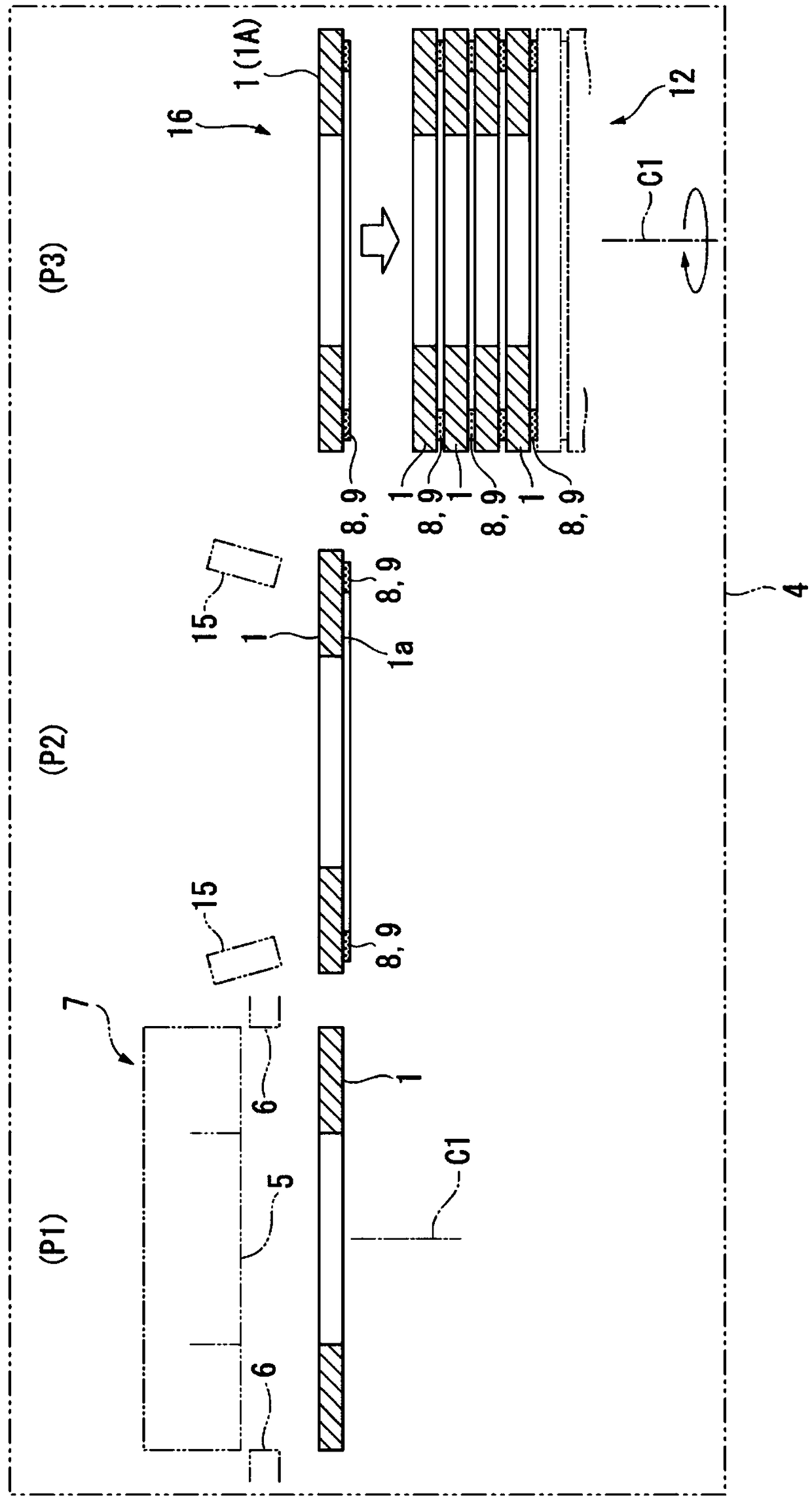
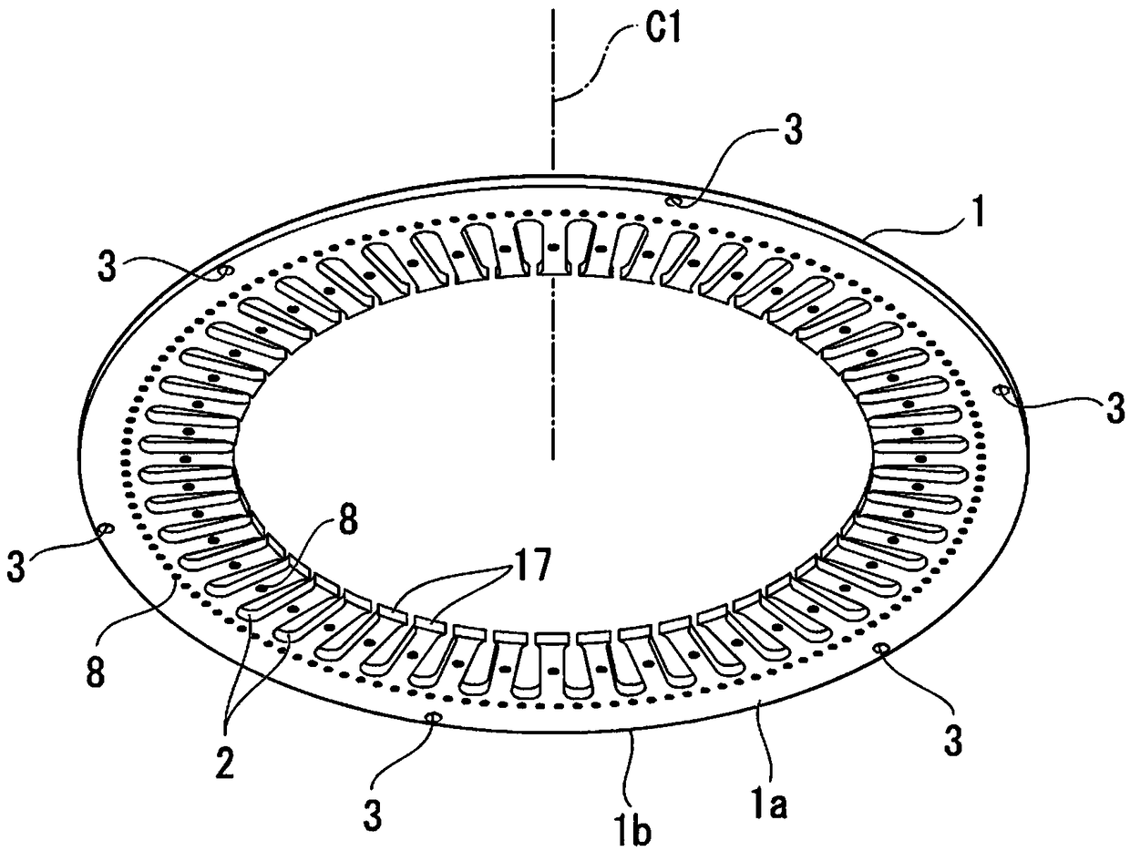
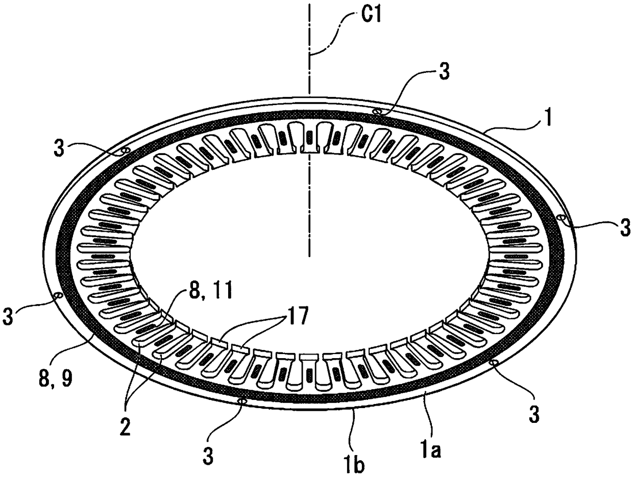
[0088] Figure 5A It is a perspective view showing the structure of the laminated body obtained by the manufacturing method of Example 1. Figure 5B It is a perspective view which schematically shows an adhesive bond layer. It should be noted that, in Figure 5A In, the adhesive agent 8 coated in dots by the second process P2 is shown (refer to Figure 2A ) is extruded and expanded in the third step P3 to form a continuous shape in the circumferential direction around the central axis C1.

[0089] Such as figure 1 As shown, the steel plate is introduced into the manufacturing apparatus 4, and the ring-shaped plate 1 is obtained by punching (first process P1).

[0090] Such as Figure 2A As shown, the adhesive 8, which is an acrylic anaerobic adhesive (room temperature curable), is applied at two places corresponding to the teeth 17, and one place is applied between adjacent teeth 17, and Each is applied in dots at equal intervals along the direction around the central ax...


PUM


Abstract

Provided is a method of manufacturing laminated steel plates by laminating a plurality of steel plates, the method including an application process of applying an adhesive agent on a surface of each of the steel plates, and a lamination process of laminating a steel plate, to which the adhesive agent is applied, and another steel plate while shifting positions of the steel plates about an axis with each other, and causing the steel plate to adhere to a laminated body using the adhesive agent, wherein, in the application process, the adhesive agent is applied such that the adhesive agent becomes in a shape that is continuous about a central axis when the steel plate and the other steel plate are adhered by the adhesive agent in the lamination process.

Description

technical field [0001] The present invention relates to a manufacturing method and manufacturing apparatus of laminated steel sheets. Background technique [0002] An electric motor used in a hybrid vehicle or the like includes, for example, a rotor and a stator that generates a rotating magnetic field. The stator core of the stator is formed of laminated steel plates obtained by laminating steel plates. The plurality of steel plates constituting the laminated steel plate are fixed to each other by forming caulked portions, bonding with an adhesive, or the like (see Japanese Patent Application Laid-Open No. 2007-159300 and Japanese Patent Laid-Open No. 2009-5539). [0003] The stator core is produced, for example, as follows. A ring-shaped steel plate is produced by punching or the like, and a plurality of (for example, tens to hundreds of) steel plates are stacked. For the purpose of making the stacked thickness of the steel plates uniform in the circumferential directio...

Claims


Application Information

Patent Timeline
Patent Type & Authority Applications(China)
IPC IPC(8): B32B37/12
CPCB32B37/12H02K1/16H02K1/185H02K15/028H02K1/18H02K15/03H01F41/0233Y10T29/49078H01F41/0213Y10T29/49009Y10T29/49012H01F41/0226H02K3/02H02K3/04
Inventor 滨村刚樱田学二宫健太西中耕一
Owner HONDA MOTOR CO LTD
Why Eureka
Try Eureka