Magnetic Device

Active Publication Date: 2013-03-07
SEH LTD
View PDF5 Cites 3 Cited by
  • Summary
  • Abstract
  • Description
  • Claims
  • Application Information

AI Technical Summary

Benefits of technology

[0031]The oscillating movement of the translator may also be brought about by a system exercising a mechanical constraining force. By coupling the translator to a system exercising a mechanical constraining force, such as a crank mechanism, it becomes possible to limit the amplitudes of the translator's oscillating movement.
[0032]The system exercising a mechanical constraining force may balance the magnetic field strengths, which may be different or the same, and their influence on the translator's movement. The invention described below is based on trials usin

Problems solved by technology

The translators are moved laterally along the stators, which results in the resulting forces between stators and translators not being parallel to the movements of the translators.
When using a magnet

Method used


Image

  • Magnetic Device
  • Magnetic Device
  • Magnetic Device

Examples


Embodiment Construction

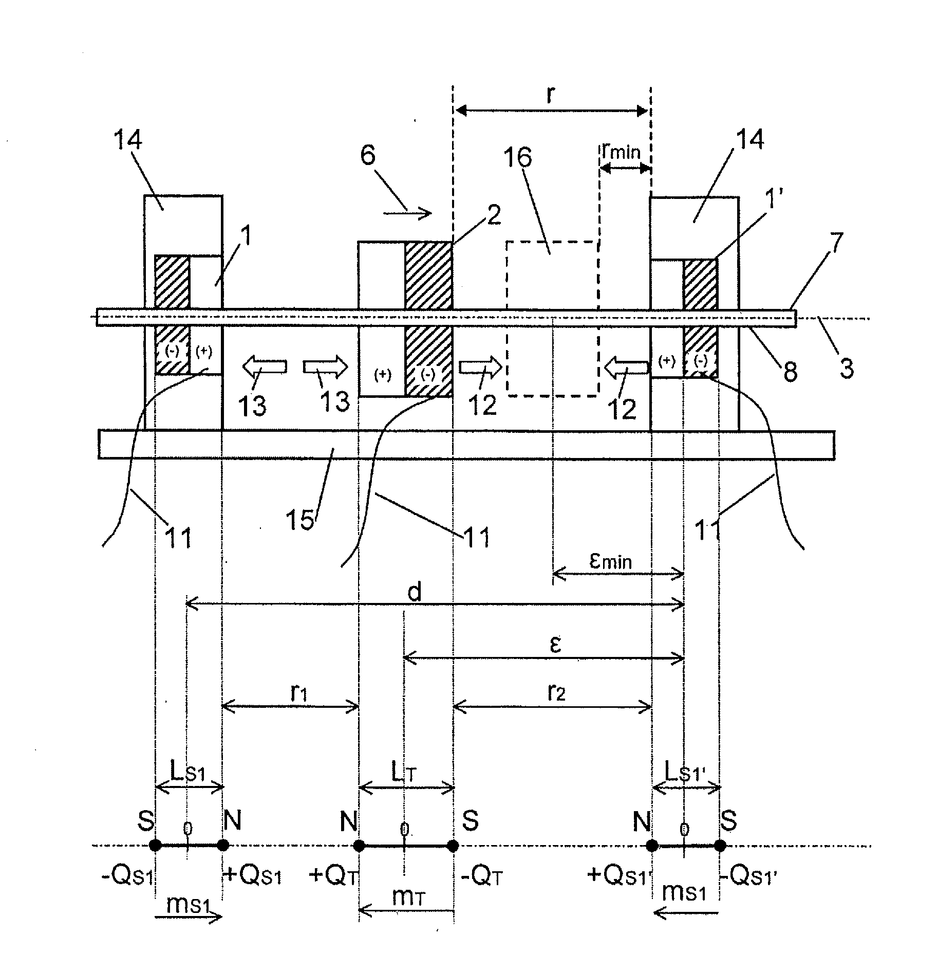
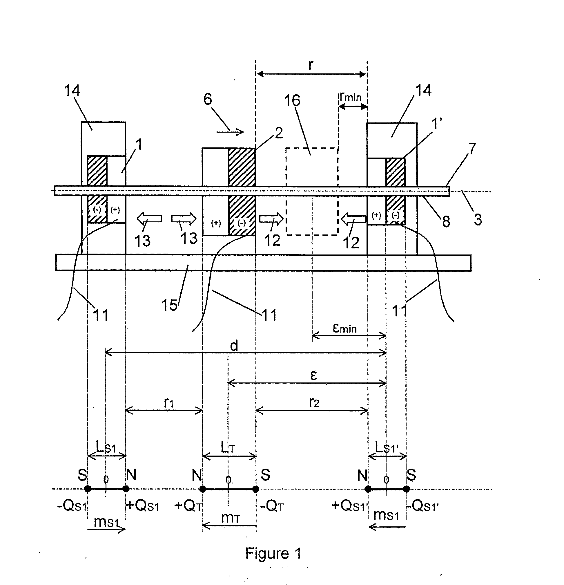
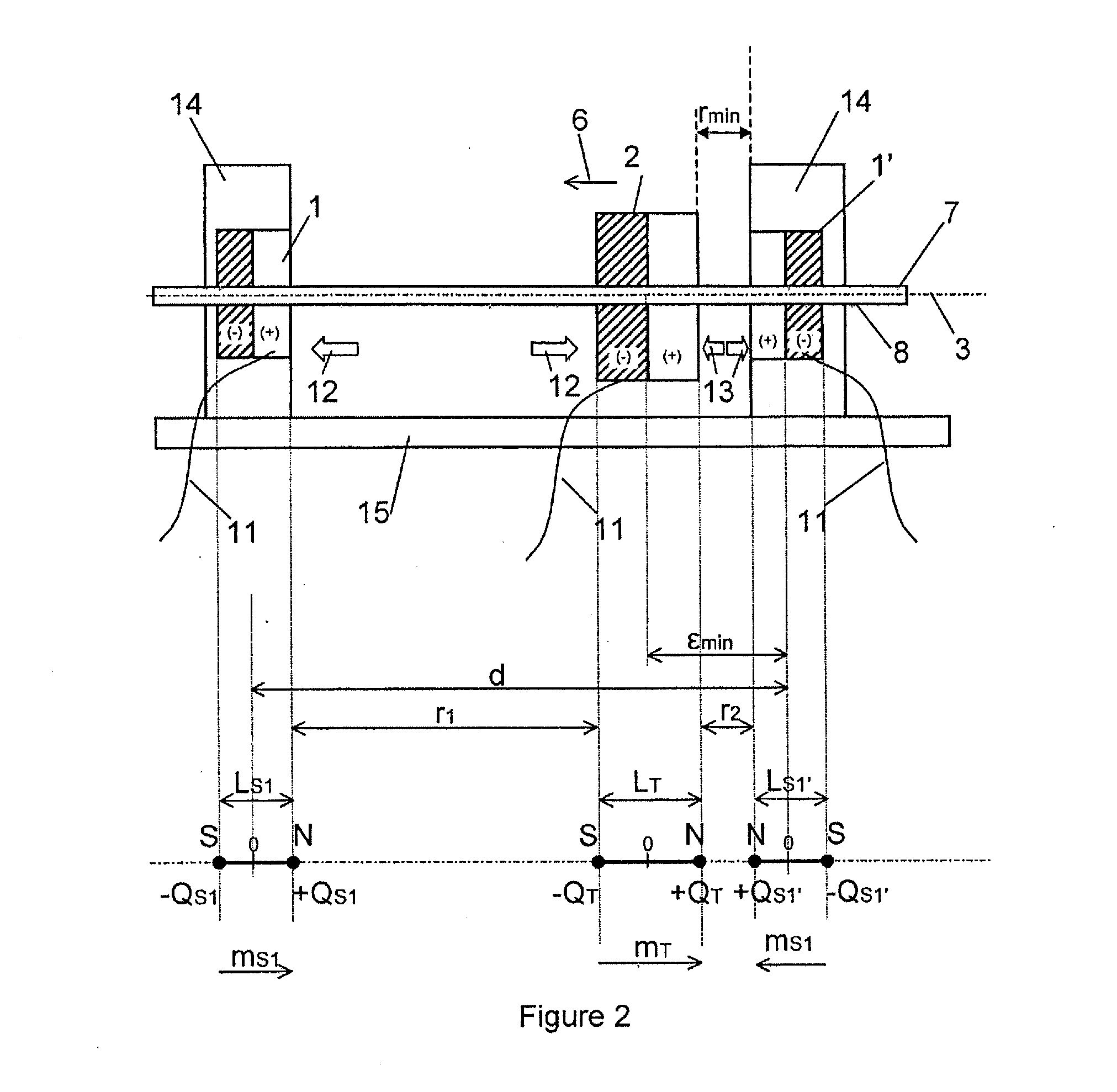
[0196]The FIGS. 1 and 2 show an embodiment of the magnetic device of the present invention as a magnetic drive 20 and all the variables used in the specification. The magnetic drive 20 comprises a translator 2 and stators 1, 1′ which are disposed laterally in relation to the translator 2. The stators 1, 1′ and the translator are electromagnets which are oriented along an axis—in the embodiment exemplarily shown in the FIGS. 1 and 2 along the driving axle of the translator 3. The dipolar moment of the stators 1, 1′ and the translator 2 is parallel to said axis.

[0197]In order to provide for an alternating polarization of the translator 2, said translator 2 is connected to an a.c. power source (not represented) via a power cable 11, while each of the stators 1, 1′ is connected to a d.c. source (not represented) via further power cables 11.

[0198]The polarization of the translator 2 is selected, so that the pole of the translator 2 facing the left stator 1 is polarized the same way as th...


PUM


Abstract

A magnetic device includes at least one stator and at least one translator. The translator is moveable in relation to the stator in a translator moving direction. The translator moves in a direction oriented towards the stator. The at least one stator and the translator are arranged along an axis. The magnetic device includes a control device, the control device includes a device for controlling a distance r≧0 (r being equal to or greater than 0) between the translator and the stator in relation to the force generated between the stator and the translator when the magnetic device is in operation. The translator is movable in relation to the stator in the translator moving direction along a linear translator movement axis. The at least one stator and the translator are oriented along the translator moving axis.

Description

CROSS-REFERENCE TO RELATED APPLICATIONS[0001]This application is a non-provisional of U.S. Provisional Patent Application No. 61 / 552,089, filed Oct. 27, 2011, which is incorporated herein by reference. This application also claims the benefit of Austrian Patent Application No. A 1260 / 2011, filed Sep. 5, 2011, which is incorporated herein by reference.BACKGROUND[0002]1. Field[0003]The present invention relates to a magnetic device comprising at least one stator magnet and at least one translator magnet, said translator being movable in relation to said stator in a translator moving direction, said translator moving direction being oriented directionally towards the stator, said translator being further coupled to a driving axle.[0004]2. Description of the Related Art[0005]According to the state of the art, magnetic drives are based on the principle of utilizing the magnetic dipole. By activating repulsive and attractive forces, the translator is caused to move in relation to the stat...

Claims


Application Information

Patent Timeline
IPC IPC(8): H02K41/02
CPCH01F7/1646H02K33/16H02K2201/03H01F2007/185H02K2213/09H01F2007/1692H01F7/1844H02K2213/03
Inventor HEIN, JEREMYMARSCHNER VON HELMREICH, MARTIN
Owner SEH LTD
Why Eureka
Try Eureka