Al technical title is built by PatSnap Al team. It summarizes the technical point description of the patent document.
a lighting system and light box technology, applied in lighting and heating apparatus, lighting support devices, instruments, etc., can solve the problems of relatively low electrical efficiency, and relatively short lifespan of light sources, and achieve cost-effective effects
Active Publication Date: 2013-03-07
THE SLOAN COMPANY INC DBA SLOANLED
View PDF3 Cites 15 Cited by
Summary
Abstract
Description
Claims
Application Information
AI Technical Summary
This helps you quickly interpret patents by identifying the three key elements:
Problems solved by technology
Method used
Benefits of technology
[0016]The invention provides various embodiments of a lighting unit, systems and methods of manufacturing the same. The invention is configured to be efficient, reliable, cost effective and can be arranged to provide illumination for structural lighting, display lighting and ingress/egress lighting, and is particularly applicable for light boxes o
Problems solved by technology
One of the problems associated with the conventional lighting units and systems is that their light sources can experience relatively short lifespans and they can have relatively low electrical efficiency.
Incandescent bulbs, neon bulbs and fluorescent tubes have a relatively short lifespan, particularly when compared to other light sources, such as typical LEDs.
These light sources are also electrically inefficient and providing sufficient lighting, especially in large lighting applications, requires the consumption of significant energy.
Neon bulbs can also experience difficulty with cold starting, which can lead to failure of the neon bulb.
Incandescent lights are very energy-inefficient light sources with a vast majority of the electricity they consume being released as heat rather tha
Method used
Image
Click on the blue label to locate the original text in one second.
Reading with bidirectional positioning of images and text.
Examples
Embodiment Construction
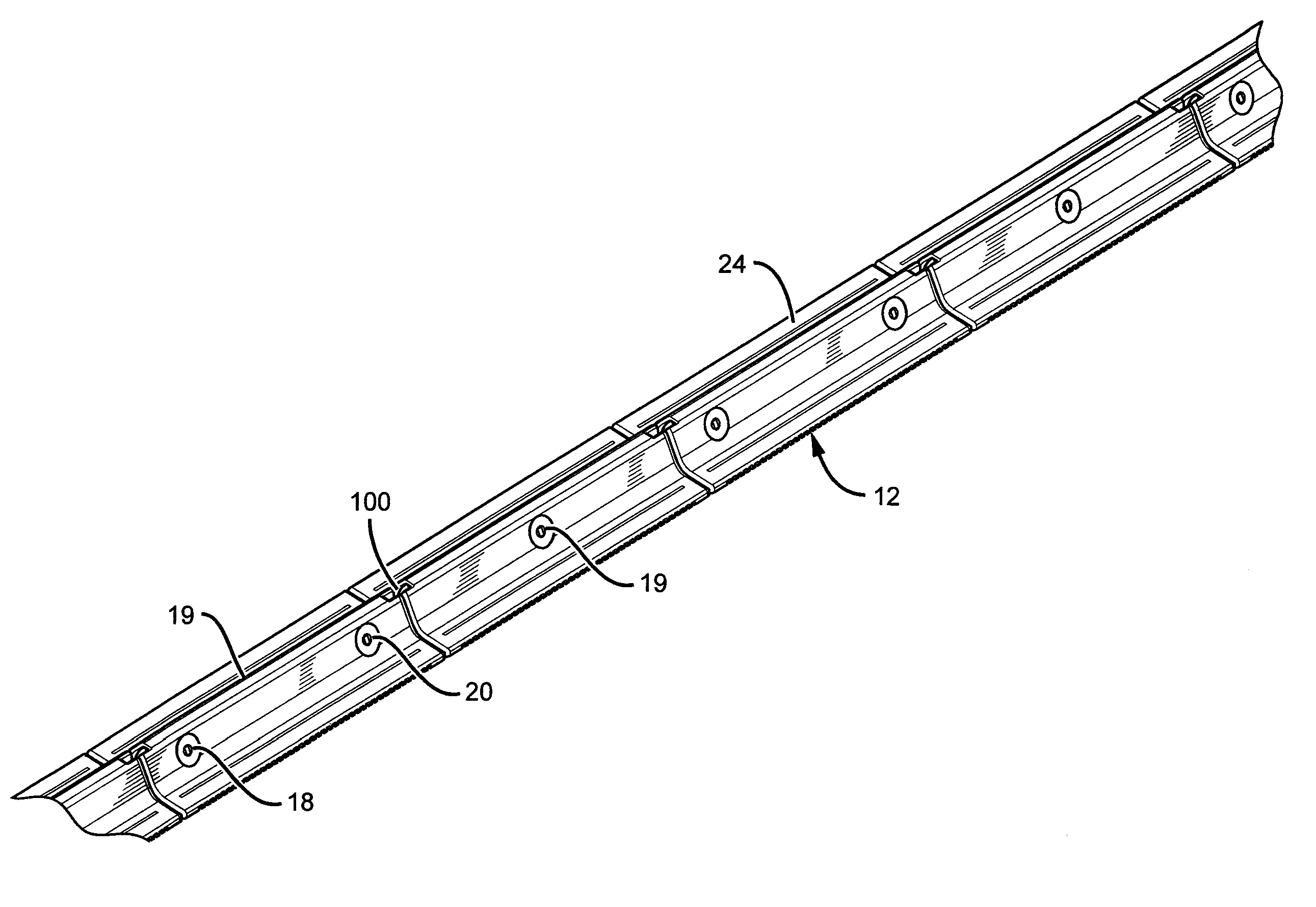
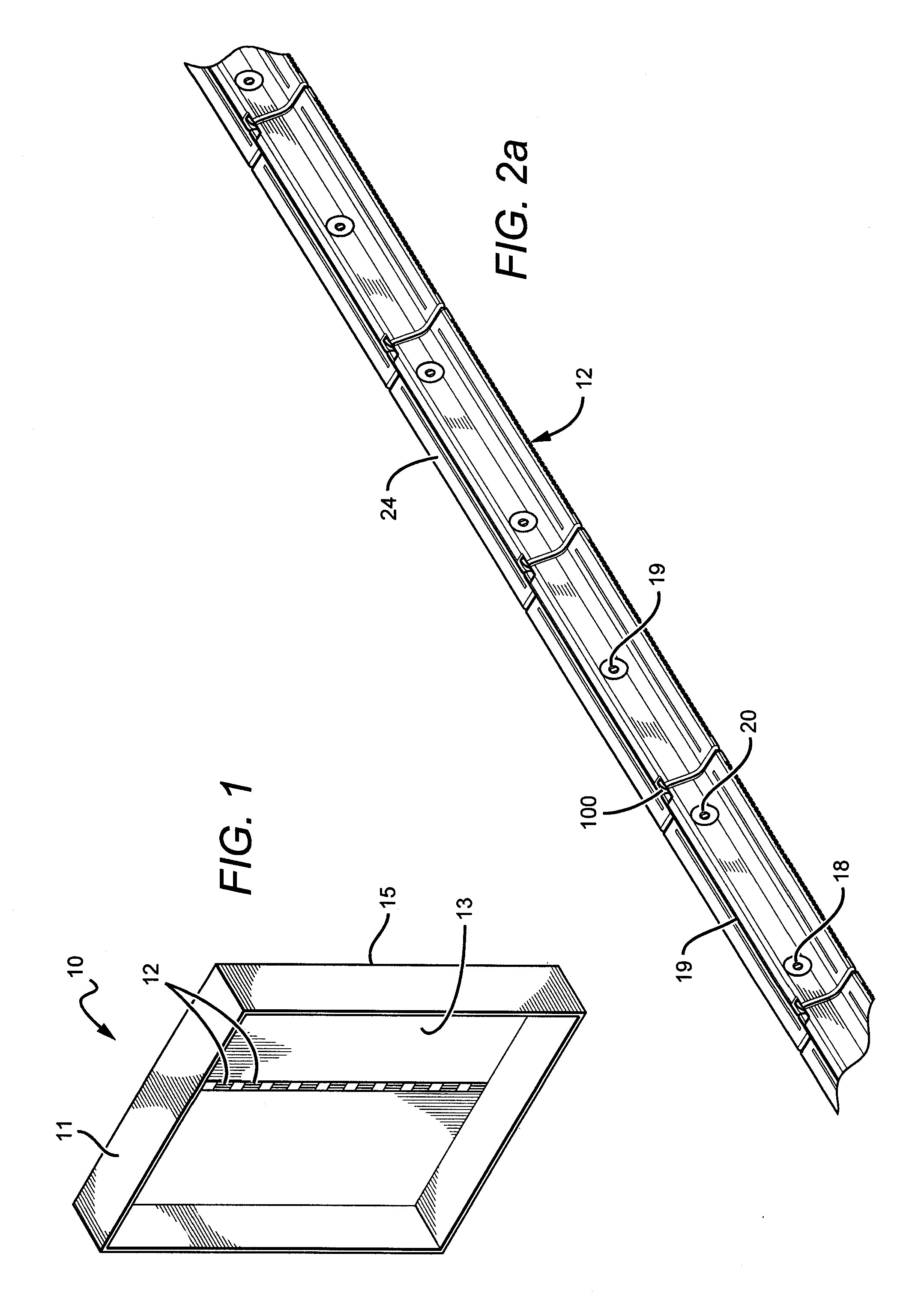
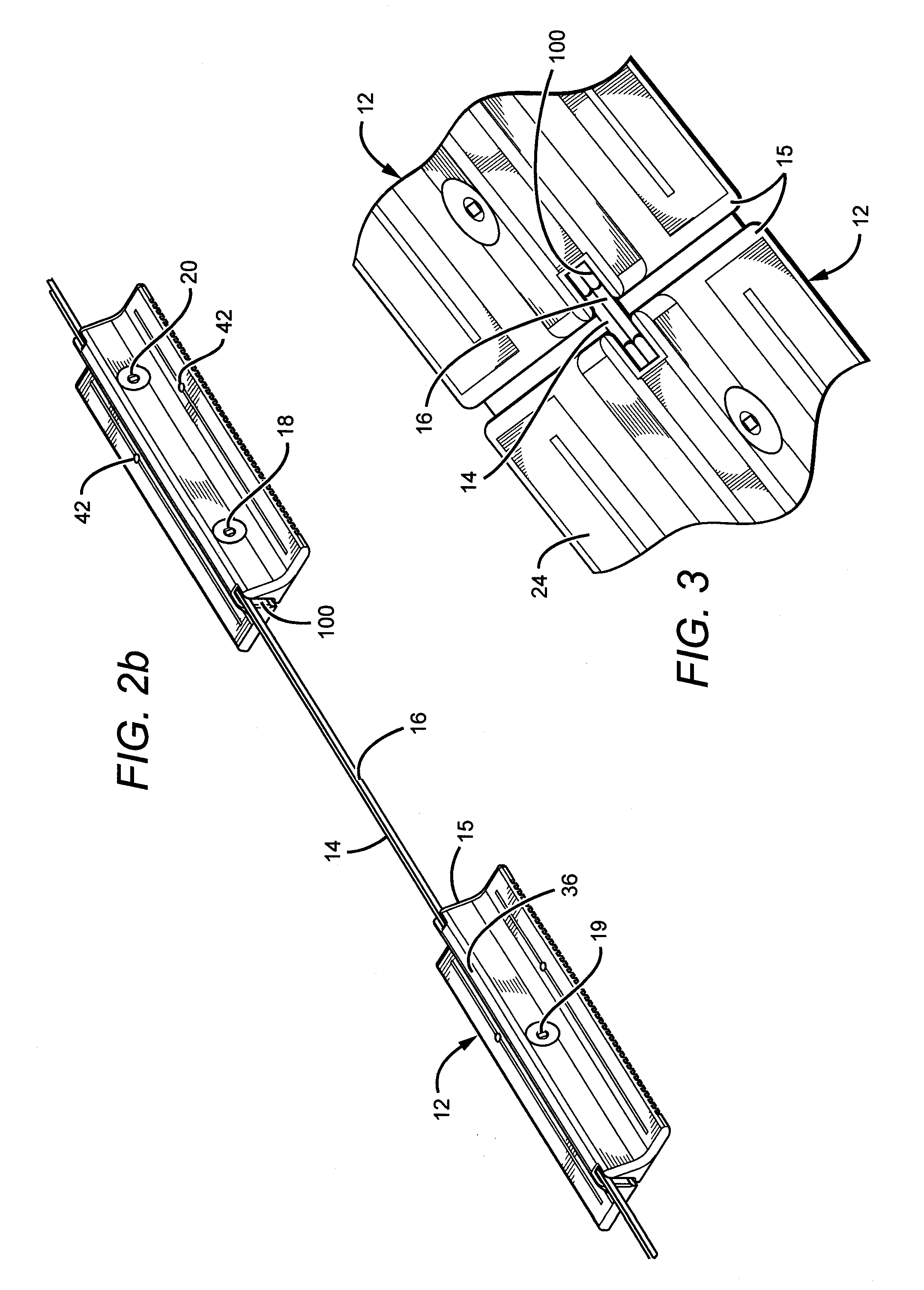
[0055]The invention described herein is directed to different embodiments of a lighting system that can be used in many different applications such as but not limited to structural lighting, display lighting and ingress / egress lighting. The lighting system according to the invention can be arranged in many different ways with many different components, and is generally arranged to provide illumination for light boxes or sign cabinets. In some embodiments, the lighting system comprises a light box housing and plurality of lighting units, wherein the plurality of lighting units are interconnected in a daisy-chain configuration. Electrical conductors are provided to each of the plurality of lighting units so that an electrical signal applied to the input end of the conductors spreads to the lighting units, causing each of the light emitting elements to emit light. The lighting unit can be mounted in various locations within the light box housing. Each of the lighting units comprises a ...
PUM
Abstract
A lighting system comprising a light box housing, a plurality of lighting units including a housing, a plurality of light emitting elements mounted on a PCB within the housing. The light emitting elements arranged on an angled surface such that the light emitting elements emit light in a sideways direction from the lighting units. The lighting units can also be interconnected in a daisy-chain configuration, such that the lighting units form a row of lighting units. The row of lighting units adapted to be mounted within the light box housing, wherein the light box housing comprises one or more rows of lighting units.
Description
RELATED APPLICATIONS[0001]This application is a continuation in part of Ser. No. 13 / 010,413 to Bruce Quaal et al., filed on Jan. 20, 2011, which claims the benefit of priority of provisional application Ser. No. 61 / 297,681, filed on Jan. 22, 2010; also a continuation in part of Ser. No. 13 / 010,703 to Bruce Quaal et al., filed on Jan. 20, 2011, which claims the benefit of priority of provisional application Ser. No. 61 / 425,713, filed on Dec. 21, 2010; also a continuation in part of Ser. No. 12 / 316,411 to Thomas C. Sloan, filed on Dec. 12, 2008; and claims the benefit of priority of provisional application Ser. No. 61 / 448,131, filed on Mar. 1, 2011. The contents of Ser. Nos. 13 / 010,413, 61 / 297,681, 13 / 010,703, 61 / 425,713, 12 / 316,411 and 61 / 448,131 are incorporated entirely herein by reference.BACKGROUND OF THE INVENTION[0002]1. Field of the Invention[0003]This invention relates to lighting units using light sources, such as but not limited to light emitting diodes (LEDs) and more part...
Claims
Application Information
Patent Timeline
Application Date:The date an application was filed.
Publication Date:The date a patent or application was officially published.
First Publication Date:The earliest publication date of a patent with the same application number.
Issue Date:Publication date of the patent grant document.
PCT Entry Date:The Entry date of PCT National Phase.
Estimated Expiry Date:The statutory expiry date of a patent right according to the Patent Law, and it is the longest term of protection that the patent right can achieve without the termination of the patent right due to other reasons(Term extension factor has been taken into account ).
Invalid Date:Actual expiry date is based on effective date or publication date of legal transaction data of invalid patent.