Time lapse observation method, and time lapse observation apparatus and multiphoton microscope used therefor

a time lapse observation and multi-photon microscope technology, applied in the field of time lapse observation method, time lapse observation apparatus and multi-photon microscope, can solve problems such as easy constant captur

Inactive Publication Date: 2013-03-14
EVIDENT CORP
View PDF1 Cites 9 Cited by
  • Summary
  • Abstract
  • Description
  • Claims
  • Application Information

AI Technical Summary

Benefits of technology

[0009]An aspect of the present invention provides a time lapse observation method matching the image capturing area with an image capturing target area on a sample set in advance, capturing an image of the image capturing target area at certain time intervals, to obtain a time lapse image includes: before a process to obtain the time lapse image for a first time, capturing an image of a reference area on the sample being a partial area of the image capturing target area or an area in a vicinity of the image capturing target area being a smaller area than the image capturing target area to obtain a reference image; storing a position and a size of the image capturing area in capturing the reference image as a reference position, reference size respectively, and before a process to obtain the time lapse image performed at certain time intervals, setting a position of the image capturing area sequentially at a plurality of different positions in the optical axis direction of an objective including the reference position and capturing an image at each of the plurality of positions to obtain a plurality of comparison target images; and matching the image capturing area in obtaining the time lapse image with the image capturing target area, based on a comparison result of the reference image and the plurality of comparison target images.

Problems solved by technology

However, since a live sample moves from an image capturing area of an apparatus, it is not easy to constantly capture an image of the image capturing target area of the sample while matching the image capturing area that is actually captured in the image capturing and the image capturing target area of the sample.

Method used


Image

  • Time lapse observation method, and time lapse observation apparatus and multiphoton microscope used therefor
  • Time lapse observation method, and time lapse observation apparatus and multiphoton microscope used therefor
  • Time lapse observation method, and time lapse observation apparatus and multiphoton microscope used therefor

Examples


embodiment 1

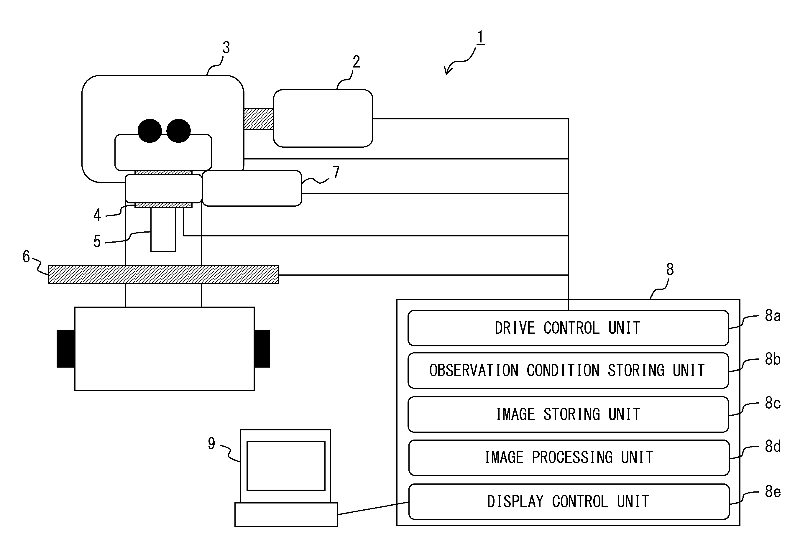
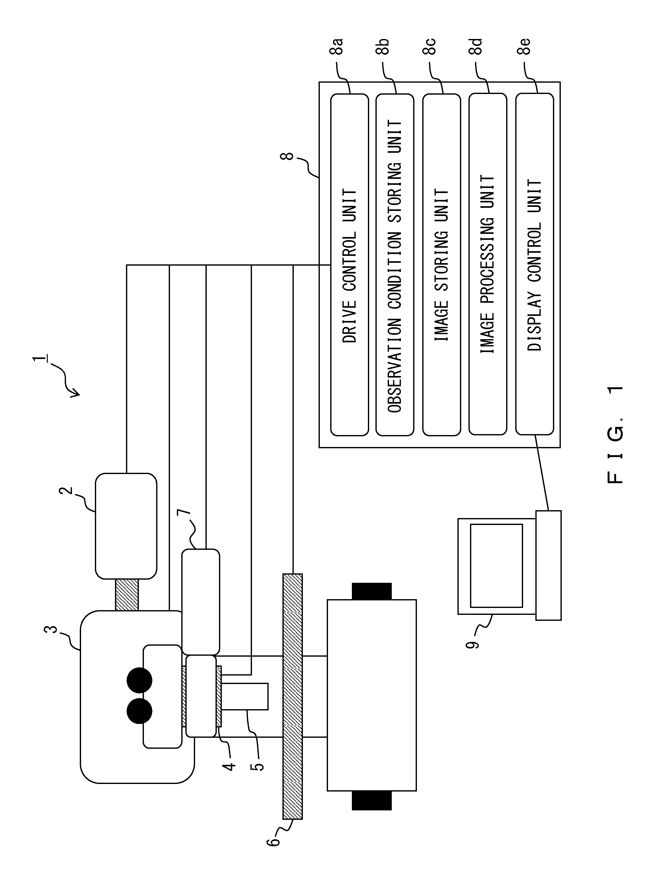
[0023]FIG. 1 is a diagram illustrating the configuration of a time lapse observation apparatus according to the present embodiment. First, with reference to FIG. 1, the configuration of a time lapse observation apparatus 1 according to the present embodiment is explained.

[0024]The time lapse observation apparatus 1 according to the present embodiment illustrated in FIG. 1 is an apparatus that obtains a time lapse image by capturing an image of the image capturing target area on a sample set in advance at certain time intervals. The sample is, for example, a biological sample that has a cell that emits fluorescence and collagen. In that case, the time lapse observation apparatus 1 is, for example, a second harmonic generation microscope or a multiphoton microscope, and the image (including time lapse image, reference image, and comparison target image described later) obtained by the time lapse observation apparatus 1 is an SHG image, a fluorescent image and the like.

[0025]The Time l...

embodiment 2

[0090]FIG. 7 is a flowchart presenting the process of the time lapse observation performed in the time lapse observation apparatus according to the present embodiment. FIG. 8 is a diagram for explaining the setting process of the reference area performed before obtaining the time lapse image in the time lapse observation apparatus according to the present embodiment. The time lapse observation apparatus according to the present embodiment differs from the time lapse observation apparatus 1 according to embodiment 1 in setting an area outside the image capturing target area as the reference area. The configuration of the time lapse observation apparatus according to the present embodiment is the same as the configuration of the time lapse observation apparatus 1.

[0091]Hereinafter, with reference to FIG, 7 and FIG. 8, the process flow of the time lapse observation apparatus according to the present embodiment is explained specifically focusing on the difference from the process flow i...

embodiment 3

[0100]FIG. 9 is a flowchart presenting the process of the time lapse observation performed in the time lapse observation apparatus according to the present embodiment. The time lapse observation apparatus according to the present invention differs from the time lapse observation apparatus 1 according to embodiment 1 in updating the reference image by the comparison target image identified as the image with the highest correlation. The configuration of the time lapse observation apparatus according to the present embodiment is the same as the configuration of the time lapse observation apparatus 1.

[0101]Hereinafter, with reference to FIG. 9, the process flow of the time lapse observation apparatus according to the present embodiment is explained specifically focusing on the difference from the process flow in the time lapse observation apparatus 1 according to embodiment 1 illustrated in FIG. 4. Meanwhile, the same step number is assigned to the same process as the process described ...


PUM


Abstract

Time lapse observation method includes: before a process to obtain a first time lapse image, capturing an image of a reference area on a sample being a partial area of a target area or an area in a vicinity of the target area being a smaller area than the target area to obtain a reference image; storing a position of a capturing area in capturing the reference image as a reference position; before a process to obtain the time lapse image performed, setting a position of the capturing area sequentially at different positions in the optical axis direction of an objective including the reference position and capturing an image at each of the positions to obtain comparison target images; and matching the capturing area with the target area, based on a comparison result of the reference image and the comparison target images.

Description

BACKGROUND OF THE INVENTIONCross-reference to Related Application[0001]This application is based upon and claims the benefit of priority from prior Japanese Patent Application No. 2011-198861, filed Sep. 12, 2011, the entire contents of which are incorporated herein by this reference.[0002]1. Field of the Invention[0003]The present invention relates to a time lapse observation method, and a time lapse observation apparatus and a multiphoton microscope, especially a time lapse observation method used in the in vivo observation, and a time lapse observation apparatus and a multiphoton microscope used for it.[0004]2. Description of the Related Art[0005]In the in vivo observation whose importance has been recognized in the field of biological studies, the time lapse observation has been performed generally to record the activity and change of a live sample.[0006]Incidentally, in the time lapse observation, it is desirable in observing the activity and change of a sample to capture image...

Claims


Application Information

Patent Timeline
Patent Type & Authority Applications(United States)
IPC IPC(8): H04N5/76H04N7/18
CPCG02B7/365G02B21/0076H04N9/8205G02B21/367G02B21/0084
Inventor NAKASHO, EIJI
Owner EVIDENT CORP
Why Eureka
Try Eureka