
Method and system for associating devices with a coverage area for a camera

Inactive Publication Date: 2013-03-14
SCHNEIDER ELECTRIC IT CORP
View PDF6 Cites 12 Cited by
  • Summary
  • Abstract
  • Description
  • Claims
  • Application Information

AI Technical Summary

Benefits of technology

The patent discusses the problem of displaying and representing monitoring data to end-users in data center management systems. These systems typically only show a list of camera feeds and alarms, making it difficult for users to quickly find out more information about the source of the alarms. This can lead to elevated security risks and potential damage to the equipment. The technical effect of the patent is to provide a more efficient and effective way of displaying and managing monitoring data in data center management technology.

Problems solved by technology

However, many typical systems for remotely monitoring locations and equipment suffer from deficiencies associated with displaying and representing monitoring data to end-users.
However, such views are often limited to displaying lists of camera and visual feeds available from those cameras.
Failure to understand the cause of an alarm may lead to elevated security risks or potential damage to the equipment.

Method used


Image

  • Method and system for associating devices with a coverage area for a camera
  • Method and system for associating devices with a coverage area for a camera
  • Method and system for associating devices with a coverage area for a camera

Examples


Embodiment Construction

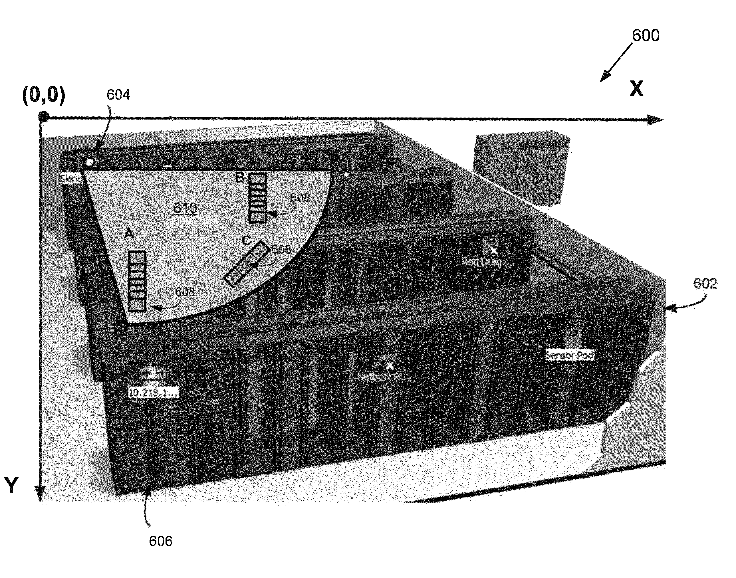
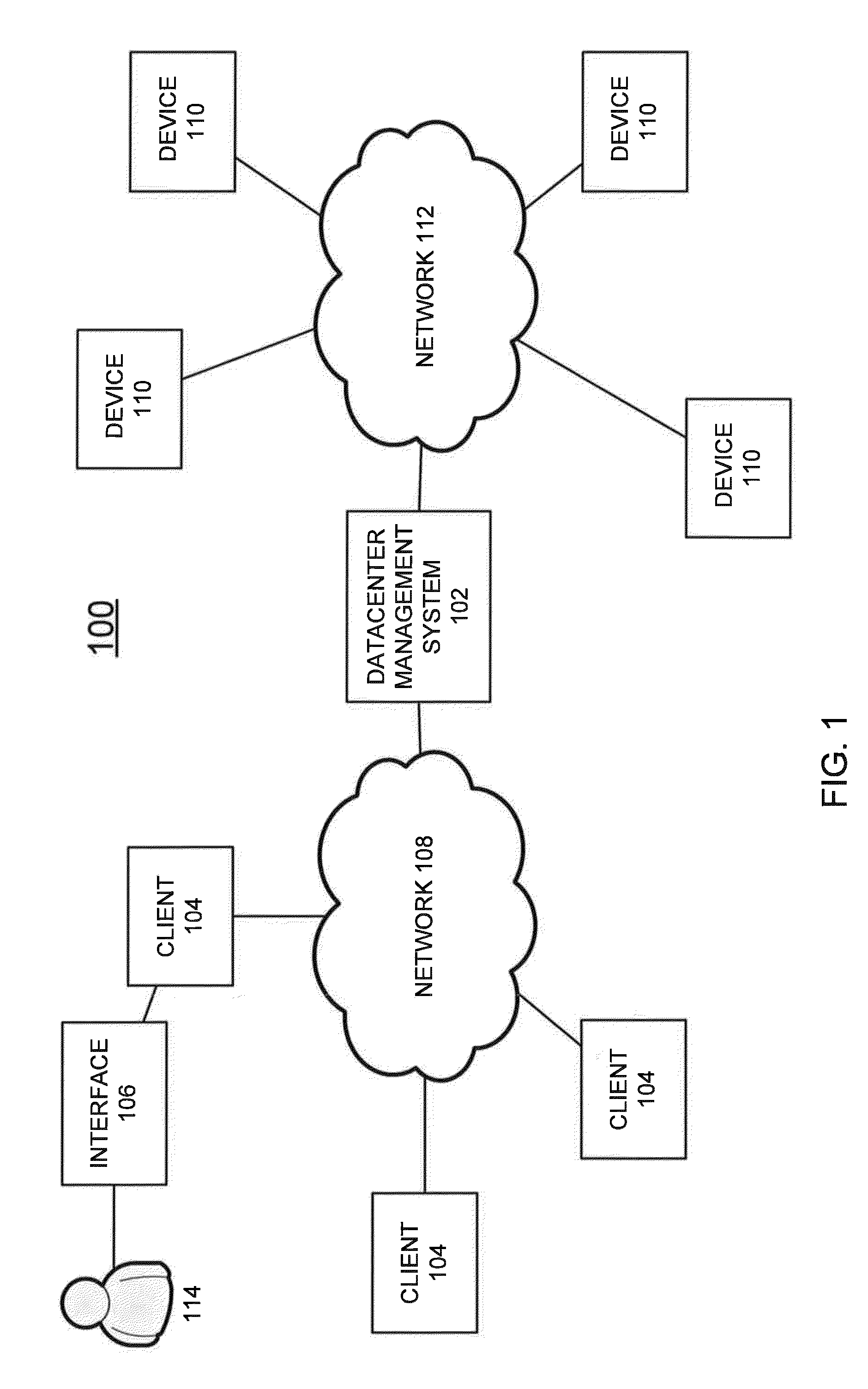
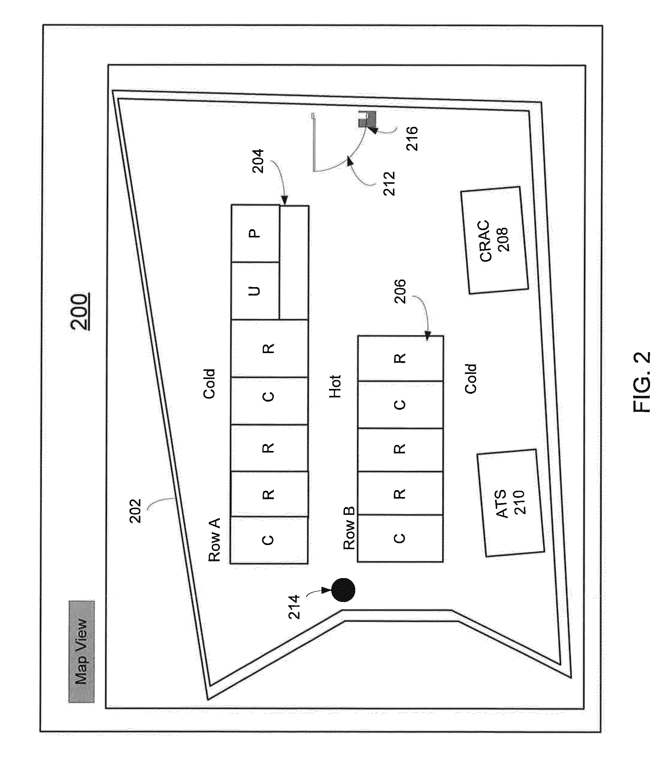
[0028]Systems and methods provided herein present camera images to end-users in a way that minimizes manual search and maximizes response from data center personnel. Users of the system and methods provided herein can determine and eliminate areas or devices in the data center without camera coverage (i.e. blind spots). At least one aspect of the present invention relates to a system and method for determining and associating devices within a camera's coverage area. Another aspect of the present invention relates to a system and method of graphically indicating the camera's coverage area in a graphical representation of the data center. Such a system or method may be implemented with respect to a data center, often using an automated centralized network manager.

[0029]It is to be appreciated that examples of the methods and apparatuses discussed herein are not limited in application to the details of construction and the arrangement of components set forth in the following descriptio...


PUM


Abstract

A system and method for managing at least one camera having a coverage area within a data center is disclosed. In one aspect, a method includes obtaining, by a computer, identification information for at least one data center device within the data center from a data center management system through a communications network, associating the at least one data center device with the at least one camera based on the identification information for the at least one data center device, and displaying at least one image captured by the at least one camera associated with the at least one data center device in response to the data center management system detecting an event associated with the at least one data center device.

Description

BACKGROUND[0001]1. Field of Invention[0002]At least one embodiment relates generally to methods and systems for obtaining images of devices in a data center, and more specifically, to a method and system for associating devices with cameras via a visual interface.[0003]2. Discussion of Related Art[0004]In response to the increasing demands of information-based economies, information technology networks continue to proliferate across the globe. One manifestation of this growth is the centralized network data center. A centralized network data center typically consists of various information technology equipment, collocated in a structure that provides network connectivity, electrical power and cooling capacity. Often the equipment is housed in specialized enclosures termed “racks” which integrate these communications, power and cooling elements. In some data center configurations, rows of racks are organized into hot and cold aisles to decrease the cost associated with cooling the in...

Claims


Application Information

Patent Timeline
IPC IPC(8): H04N7/18
CPCH04N7/181
Inventor KINGSLEY, SCOTT MICHAEL
Owner SCHNEIDER ELECTRIC IT CORP
Learn More