Backlight Module and Liquid Crystal Display

a backlight module and liquid crystal display technology, applied in the field of backlight modules and liquid crystal displays, can solve the problems of reducing the light use efficiency of the backlight module, and not having the expansion space provided for the light guide plate, so as to reduce the image displaying quality of the liquid crystal display and expand the space

Inactive Publication Date: 2013-03-14
SHENZHEN CHINA STAR OPTOELECTRONICS TECH CO LTD
View PDF8 Cites 12 Cited by
  • Summary
  • Abstract
  • Description
  • Claims
  • Application Information

AI Technical Summary

Benefits of technology

[0009]The present invention provides a backlight module and a liquid crystal display to solve the problems of the light guide plate being cracked and the image displaying quality of the liquid crystal display being lowered because of the light source and the light guide plate being directly contact each other and the expanding space of the light guide plate being eliminated in the prior art.

Problems solved by technology

Obviously, because there exists the expanding gap between the light source 11 and the light guide plate 12 and whether the size of the gap is small or greater, the partial light of the light source 11 can be leaked and cannot enter into the light guide plate 12 so that resulting in a low light entry efficiency and reducing the light use efficiency of the backlight module.
But this will result in there being no the expanding space provided for the light guide plate 12.

Method used


Image

  • Backlight Module and Liquid Crystal Display
  • Backlight Module and Liquid Crystal Display
  • Backlight Module and Liquid Crystal Display

Examples


Embodiment Construction

[0045]The following description of every embodiment with reference to the accompanying drawings is used to exemplify a specific embodiment, which may be carried out in the present invention. Directional terms mentioned in the present invention, such as “top”, “bottom”, “front”, “back”, “left”, “right”, “inside”, “outside”, “side” etc., are only used with reference to the orientation of the accompanying drawings. Therefore, the used directional terms are intended to illustrate, but not to limit, the present invention.

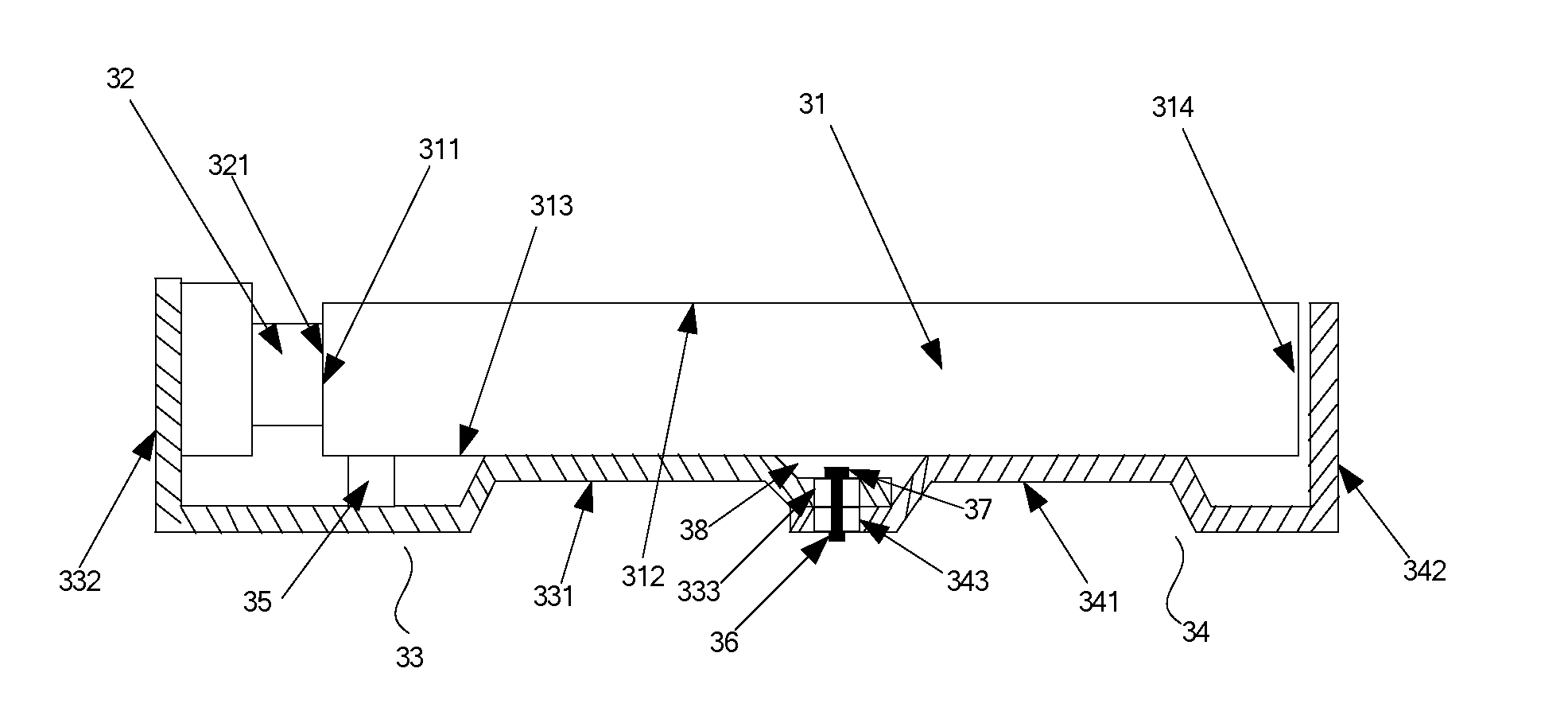
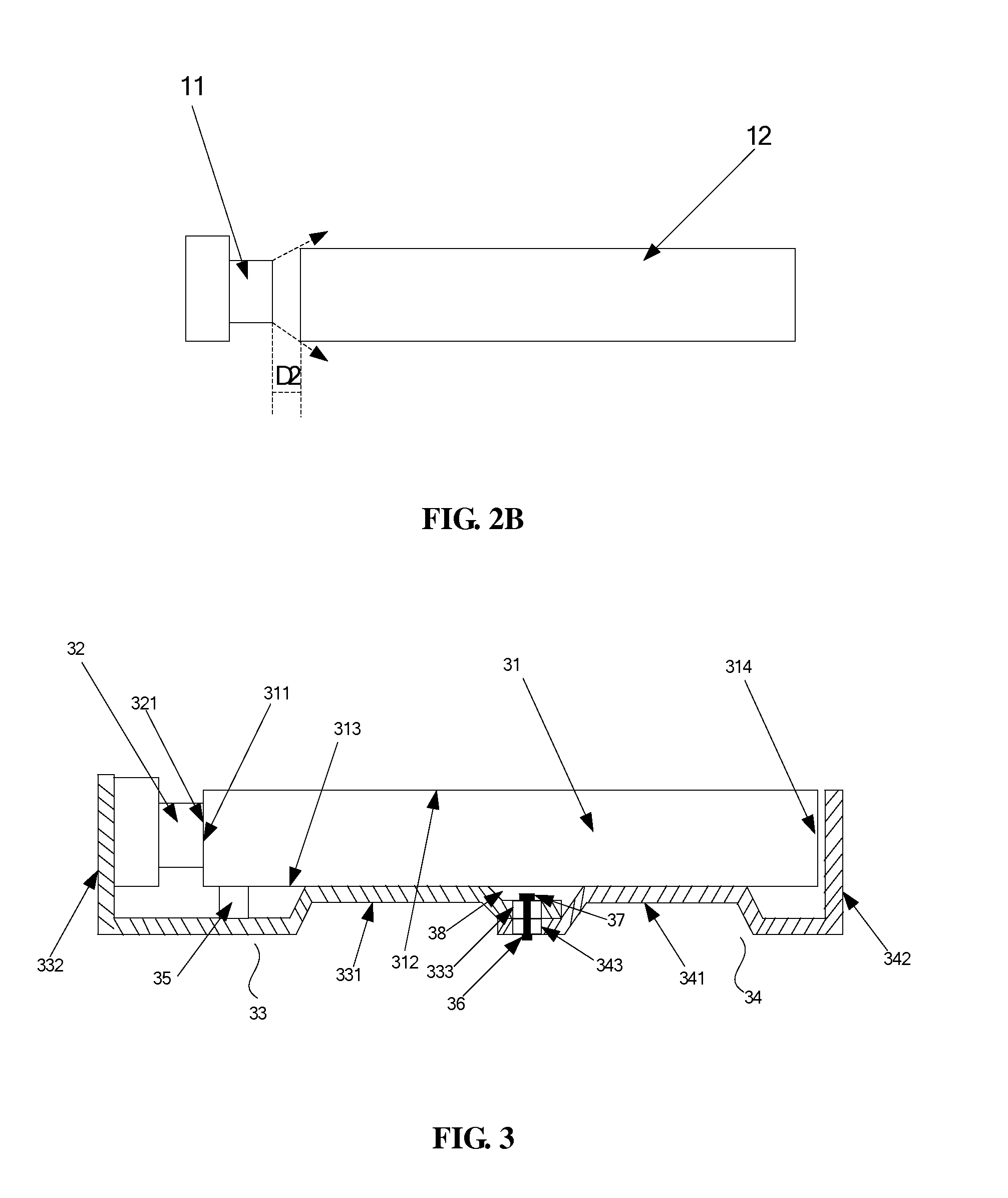
[0046]FIG. 3 is a structural view of a preferred embodiment of a backlight module of the present invention.

[0047]The backlight module comprises a light guide plate 31 and a light source 32. The light guide plate 31 extends along a horizontal plane. The light guide plate 31 includes a light incidence surface 311, a light exit surface 312 connected to the light incidence surface 311, and a bottom surface 313 opposite to the light-emitting surface 312.

[0048]Please refer to ...


PUM

PropertyMeasurementUnit
distanceaaaaaaaaaa
incidence angleaaaaaaaaaa
sizeaaaaaaaaaa

Abstract

A backlight module and a liquid crystal display are provided. The backlight module includes a light guide plate, a source, a first back plate and a second back plate. The first back plate includes a first main body and a first bending portion. The second back plate includes a second main body and a second bending portion. The first main body is slidably connected to the second main body. The light guide plate is fixedly connected to the first main body. A light-emitting surface of the light source is against a light incidence surface of the light guide plate, and another surface of the light guide plate is close to an inner side of the second bending portion. When the light guide plate expands with heat, the expanded light guide plate pushes the second bending portion to make the second back plate slide relative to the first back plate.

Description

BACKGROUND OF THE INVENTION[0001]1. Field of the Invention[0002]The present invention relates to a technology field of liquid crystal display, and more particularly to a backlight module and a liquid crystal display.[0003]2. Description of the Prior Art[0004]With the development of the liquid crystal display technology, the demand for the function of the liquid crystal display becomes more and more high.[0005]FIG. 1 is a partial structural schematic view of a backlight module of the prior art, which includes a light source 11, a light guide plate 12 and a back plate 13. The light source 11 may be a light emitting diode (LED) for emitting light. The light emitted by the light source 11 can enter into the light guide plate 12. The light-coupling efficiency between the light source 11 and the light guide plate 12 directly influences the light use efficiency of the whole backlight module.[0006]In the prior art, the light guide plate 12 is made of the macromolecule material, such as Poly...

Claims


Application Information

Patent Timeline
Patent Type & Authority Applications(United States)
IPC IPC(8): G02F1/1335G09F13/18
CPCG09F13/04G09F13/18G09F2013/049G02F1/133615G02F1/133608G02F2001/133328G02F2201/54G02B6/0091G02F2001/133314G02F1/133314G02F1/133328G09F13/049
Inventor ZHOU, GEGE
Owner SHENZHEN CHINA STAR OPTOELECTRONICS TECH CO LTD
Why Eureka
Try Eureka