Implants and Methods of Making and Using the Same

Inactive Publication Date: 2013-03-14
DESA JONATHAN
View PDF12 Cites 0 Cited by
  • Summary
  • Abstract
  • Description
  • Claims
  • Application Information

AI Technical Summary

Benefits of technology

The present invention is a new design for a joint replacement implant that is intended to reduce material failure and joint dislocation in environments that experience high levels of cyclical loading. The implant has components that allow it to be surgically implanted with minimal damage to the existing joint and provide a relatively high degree of joint movement during use. This results in a long life for the implant and reduces the likelihood of failure in the joint.

Problems solved by technology

Rheumatoid arthritis is chronic inflammatory disorder in joints and leads to cartilage deterioration over time due to pH imbalances.
Once the cartilage is destroyed, the joint loses the ability to move smoothly due to bone on bone contact.
This in turn causes patient pain.
Over time, the Swanson implant leads to material failure and joint dislocation.

Method used


Image

  • Implants and Methods of Making and Using the Same
  • Implants and Methods of Making and Using the Same
  • Implants and Methods of Making and Using the Same

Examples


example 1

Manufacture of Implants

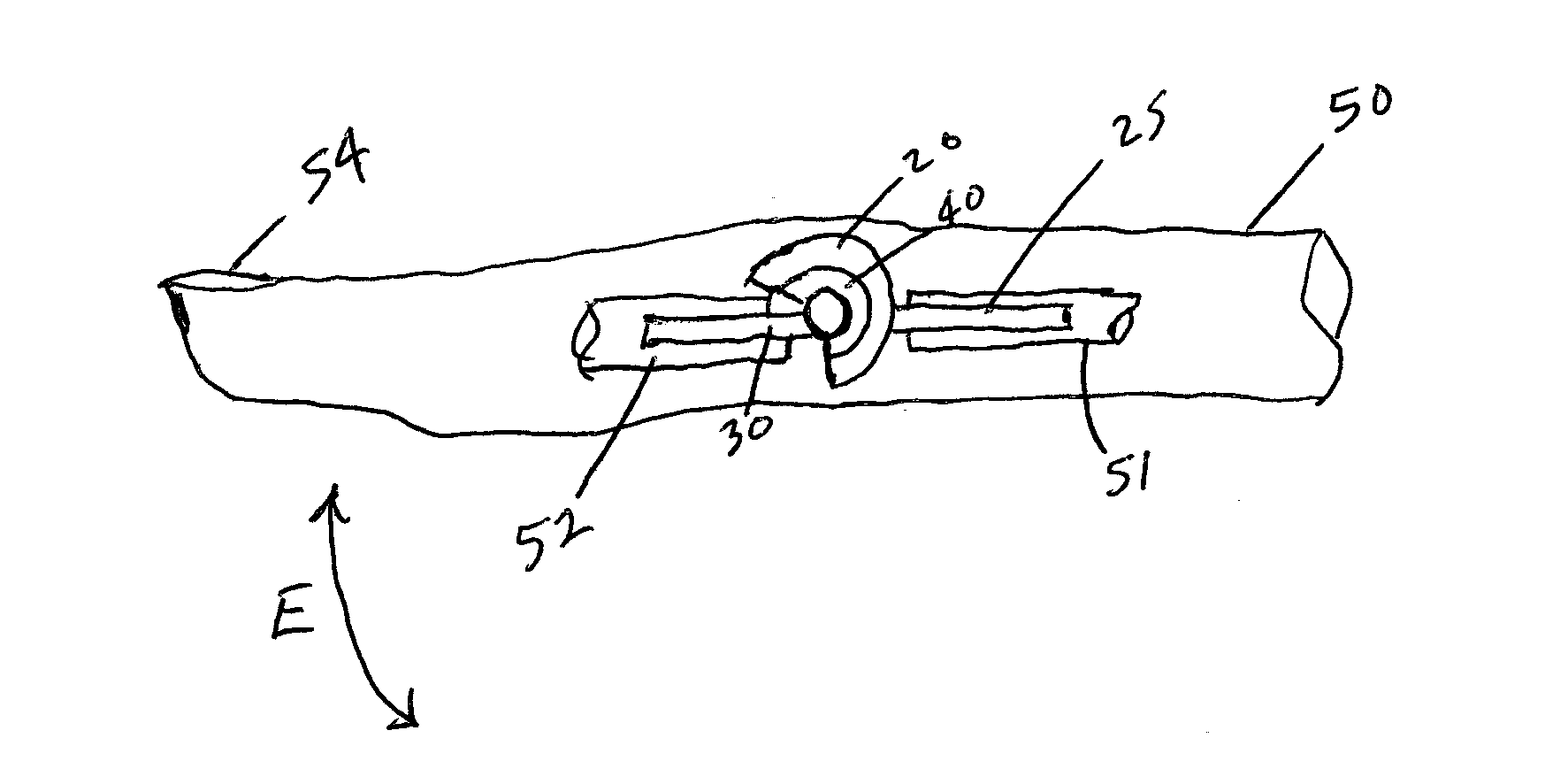
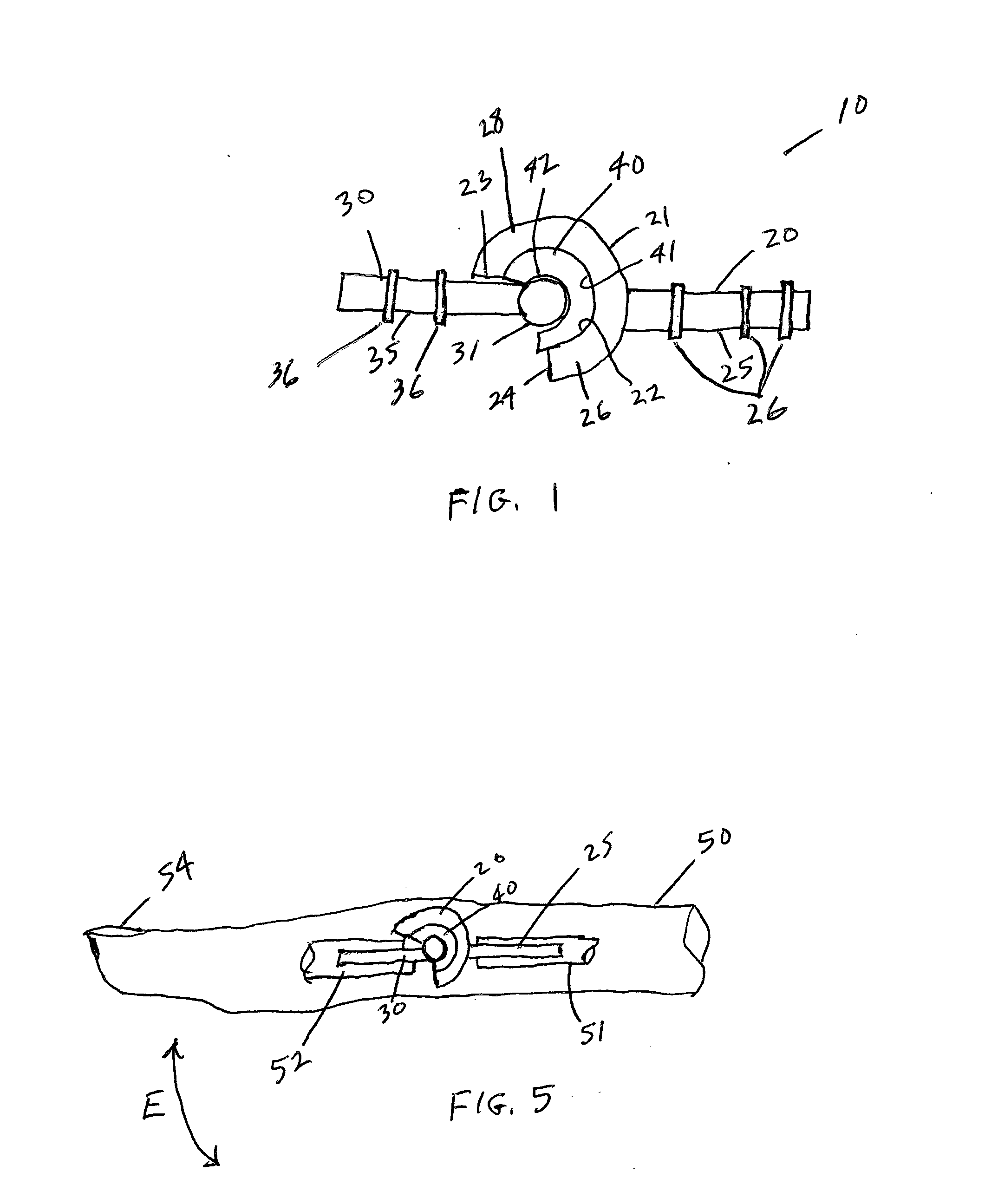
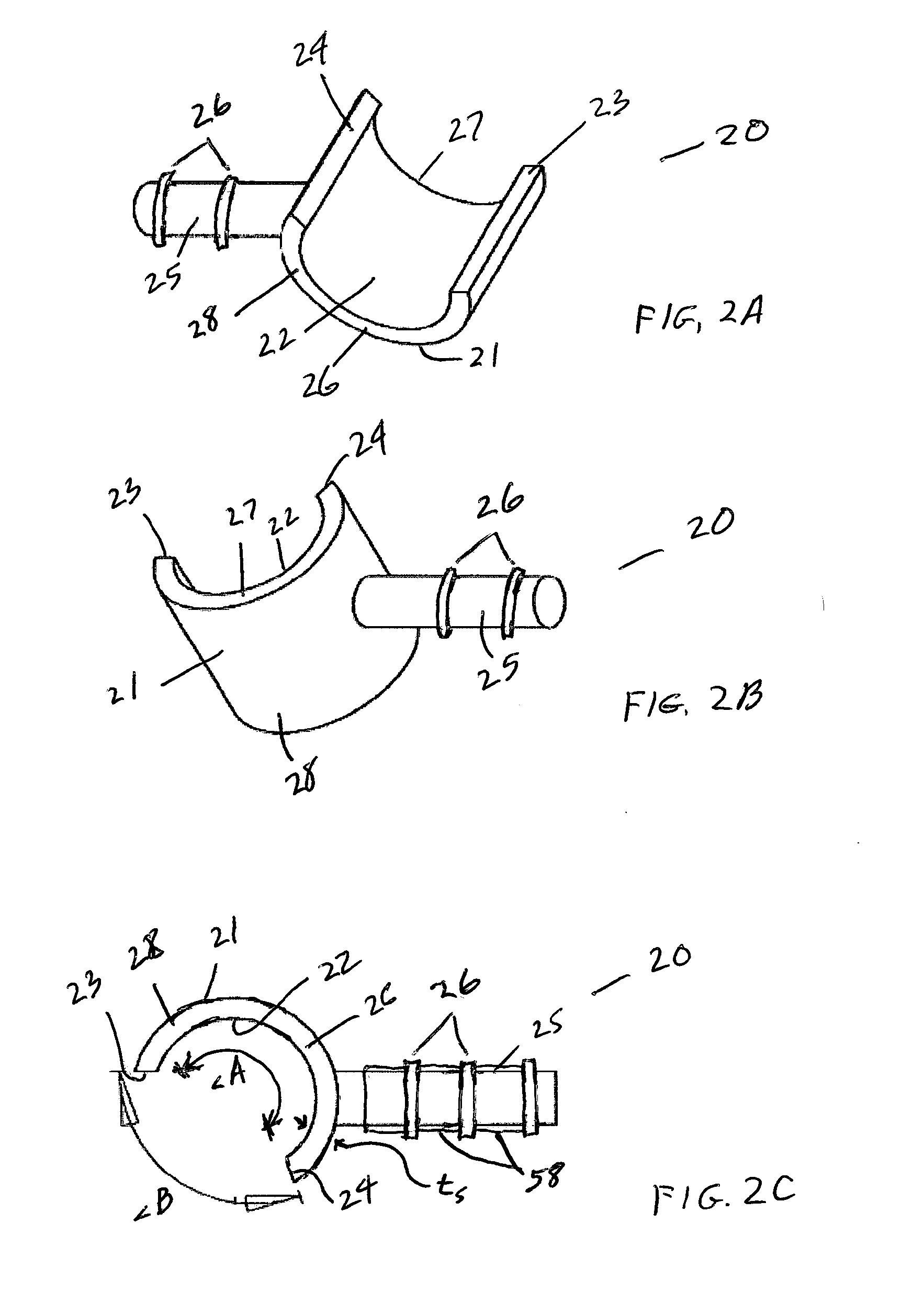
[0048]Implants, similar to implant 10 shown in FIGS. 1-5, were prepared. Engineering analysis, SolidWorks™ 3-D modeling and finite element analysis were used to optimize and validate the benefits of the implant design. All results suggested that the implant 10 design would not have a material failure in high cyclical loading environments, while restoring the natural range of motion of a joint, such as the PIP joint.

example 2

Implantation of an Implant Into a Cadaver

[0049]The following surgical procedure was utilized to implant an implant 10 of Example 1 into a cadaver. A vertical cut to the medial side of the PIP joint of the cadaver was made. Once the cut was made, the distal and proximal phalanges were bent to allow exposure of their articulating surfaces. The distal phalange was drilled and the articulating cylindrical head (e.g., distal component stem 35 of distal component 30) was implanted into the distal phalanges. The proximal phalange was drilled and the socket component (i.e., proximal stem 35 of proximal component 30) was implanted into the proximal phalange. The joint was completed by placing the articulating cylindrical head 38 of distal component 30 inside the cylindrical socket 28 of proximal component 20 with cup component 40 positioned therebetween.

[0050]After insertion, fixation, and testing, ligaments and tendons were reattached, and sutures were used to close the incision.

[0051]It sh...


PUM

PropertyMeasurementUnit
Thicknessaaaaaaaaaa
Thicknessaaaaaaaaaa
Angleaaaaaaaaaa

Abstract

Implants are disclosed. Methods of making and using implants are also disclosed.

Description

CROSS-REFERENCE TO RELATED APPLICATIONS[0001]This patent application claims the benefit of priority to U.S. Provisional Patent Application Ser. No. 61 / 573,520 filed on Sep. 8, 2011 and entitled “PROXIMAL INTERPHALANGEAL (PIP) ENDOPROSTHESIS (IMPLANT)”, the subject matter of which is hereby incorporated by reference in its entirety.FIELD OF THE INVENTION[0002]The present invention relates to implants and methods of making and using implants.BACKGROUND OF THE INVENTION[0003]Proximal interphalangeal (PIP) joint deformities occur through congenital defects, trauma, or degenerative disease, in particular, rheumatoid arthritis. Rheumatoid arthritis is chronic inflammatory disorder in joints and leads to cartilage deterioration over time due to pH imbalances. Once the cartilage is destroyed, the joint loses the ability to move smoothly due to bone on bone contact. This in turn causes patient pain. To alleviate pain due to joint damage, many patients chose to undergo an arthroplasty (i.e., ...

Claims


Application Information

Patent Timeline
IPC IPC(8): A61F2/42B23P17/04
CPCA61F2/4241A61F2002/30462A61F2002/30563A61F2002/30624Y10T29/49A61F2002/30879A61F2002/30881A61F2002/4248Y10T29/49826A61F2002/3063A61F2002/4243
Inventor DESA, JONATHAN
Owner DESA JONATHAN
Why Eureka
Try Eureka