Steering lock device

a technology of locking device and lock, which is applied in the direction of mechanical control device, anti-theft device, instruments, etc., can solve the problems of sliding machine subjected to cyclic load and shock load, and achieve the effect of attenuating impact speed and increasing action time upon collision

Inactive Publication Date: 2013-03-21
KK TOKAI RIKA DENKI SEISAKUSHO
View PDF0 Cites 5 Cited by
  • Summary
  • Abstract
  • Description
  • Claims
  • Application Information

AI Technical Summary

Benefits of technology

[0030]According to one embodiment of the invention, a steering lock device is provided with a slider cushioning mechanism that is constructed such that in order to increase the action time upon the collision from the position where a slider contacts with a lid portion of the slider cushioning mechanism until the slider reaches the inner wall of a lock body (as a stopper for the slider), the lid portion is arranged to protrude from the inner wall of the lock body via the compression coil spring by a distance L sufficient to attenuate the impact speed.

Problems solved by technology

Upon the locking of the steering shaft, the slider is subjected to a cyclic load and a shock load caused by the contact between the slider and the lock body.

Method used


Image

  • Steering lock device
  • Steering lock device
  • Steering lock device

Examples


Embodiment Construction

[0037]The preferred embodiments according to the invention will be detailed below referring to the drawings.

[0038]Overall Structure of Steering Lock Device

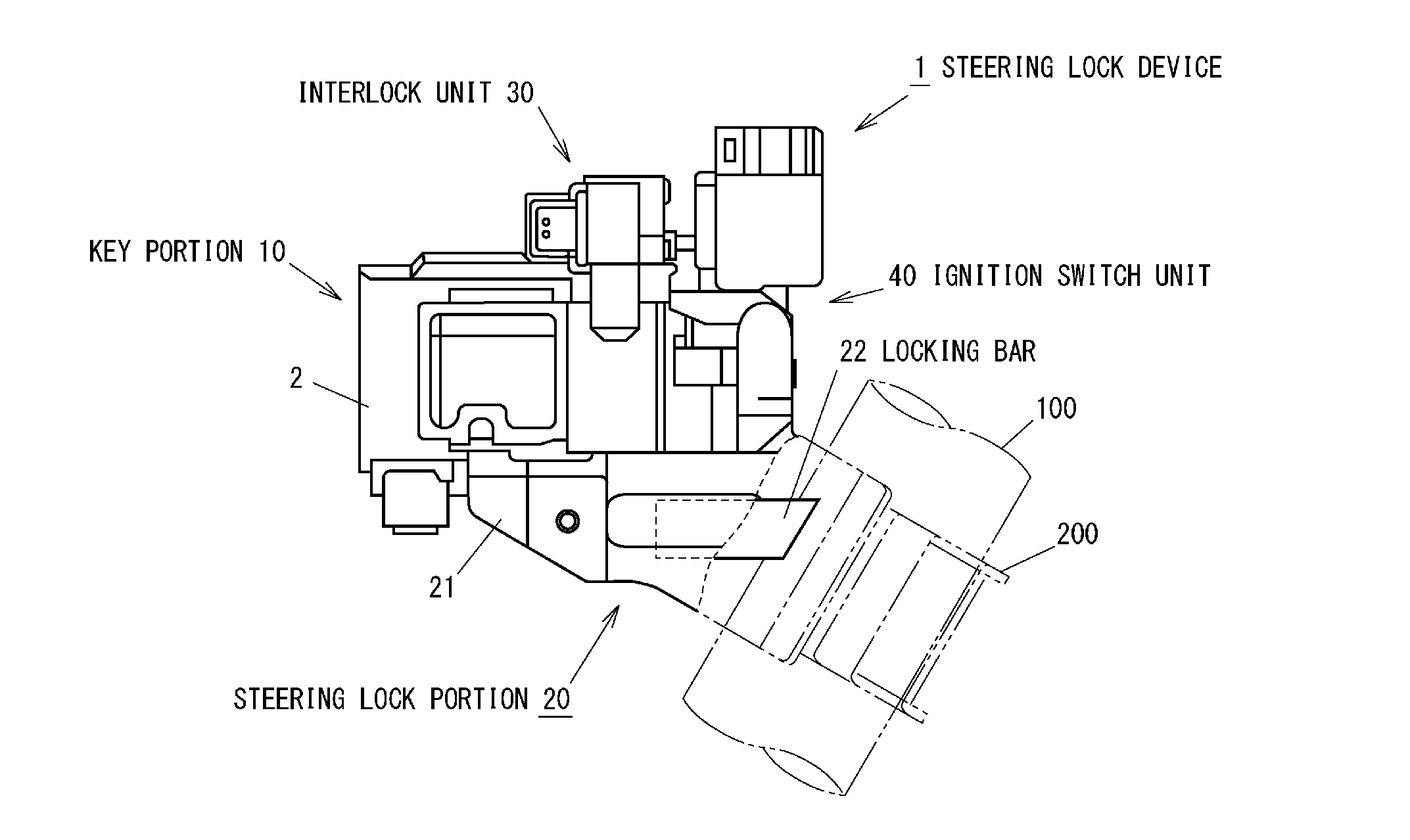
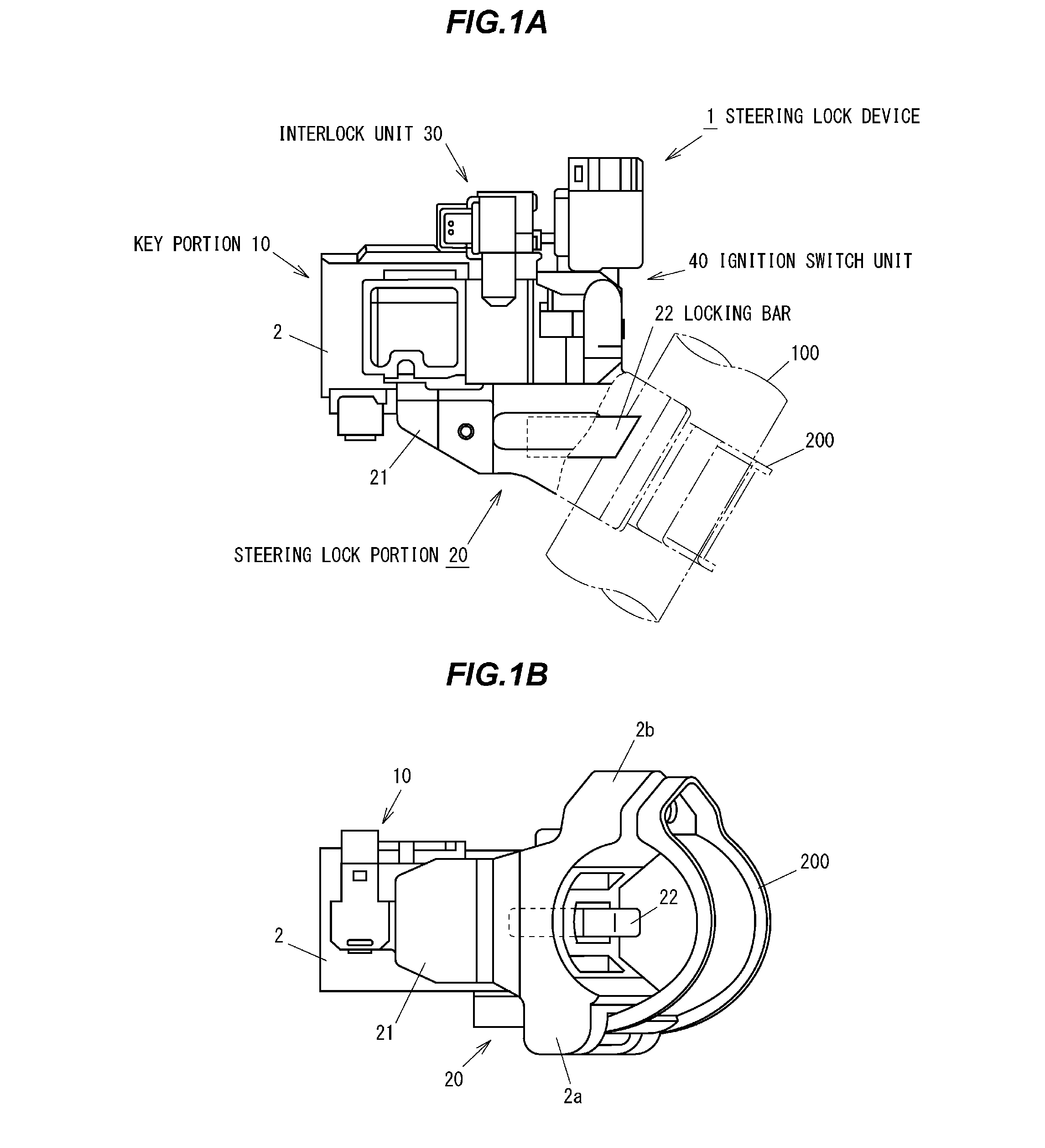
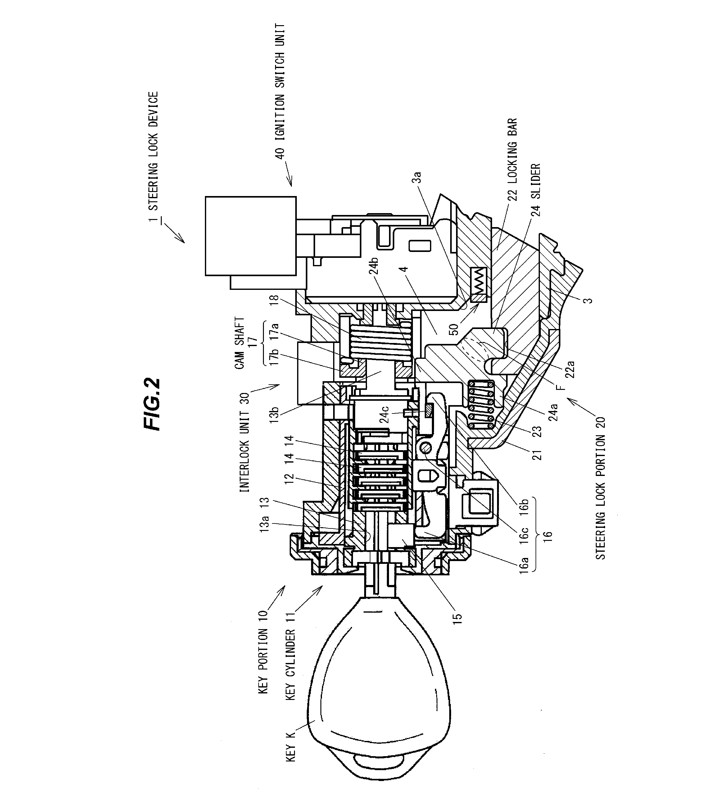
[0039]As shown in FIGS. 1A to 2, numeral 1 shows schematically the overall structure of the vehicle steering lock device. Here, in the explanation below, the insertion direction (i.e., right side in FIG. 2) of a key K is referred to “back (side)” and the removal direction (i.e., left side in FIG. 2) of the key K is referred to “front (side)”. In the front view of the key K, (the direction of) a key hole thereof is referred to vertical or horizontal.

[0040]As shown FIGS. 1A to 2, the steering lock device 1 is mainly comprised of a key portion 10, a steering lock portion 20, an interlock unit 30, and ignition switch unit 40. The steering lock device 1 has a case member 2 integrally formed of a metal material such as zinc die-cast.

[0041]As shown FIGS. 1A to 2, a protector 21 is attached to an outer wall of the case member 2 for preven...


PUM


Abstract

A steering lock device includes a rotating member to be rotated by a key, a locking member to move between a unlock position that a steering shaft is allowed to be rotated and a lock position that the steering shaft is prevented from being rotated, a sliding member to move the locking member by converting the rotation of the rotating member into a linear movement, a case member enclosing the rotating member, the locking member and the sliding member, and a cushioning mechanism disposed in an opposite wall formed in the case member, the opposite wall being opposite to a transfer space in which the sliding member is movable. The cushioning mechanism is configured to reduce an impact force generated when the sliding member contacts with the opposite wall.

Description

[0001]The present application is based on Japanese patent application No. 2011-204400 filed on Sep. 20, 2011, the entire contents of which are incorporated herein by reference.BACKGROUND OF THE INVENTION[0002]1. Field of the Invention[0003]This invention relates to a steering lock device (or steering shaft lock device) and, in particular, to a steering lock device for blocking rotation of a vehicle steering shaft (i.e., a steering wheel connected thereto).[0004]2. Description of the Related Art[0005]A vehicle steering system is provided with a steering lock device to block a turning of a steering shaft so as to prevent a vehicle theft (e.g., JP-A-2008-238950).[0006]In the steering lock device, when a key rotor with a key inserted is turned from “ACC” or “ON” position to “LOCK” position, a locking bar moves toward a steering shaft together with a slider operable to slide in a lock body to engage with the steering shaft to restrict the rotation of the steering shaft. By contrast, when...

Claims


Application Information

Patent Timeline
Patent Type & Authority Applications(United States)
IPC IPC(8): B60R25/02
CPCB60R25/02153Y10T70/5668
Inventor GOSHIMA, HIROFUMI
Owner KK TOKAI RIKA DENKI SEISAKUSHO
Why Eureka
Try Eureka