Inkjet recording apparatus

a recording apparatus and inkjet technology, applied in the direction of printing mechanisms, power drive mechanisms, printing, etc., can solve the problems of head protection members, prone to failure, and deformation of recording heads, so as to achieve adequate relative movement range and not restrict the relative movement range of recording heads.

Inactive Publication Date: 2013-03-21
RICOH KK
View PDF3 Cites 20 Cited by
  • Summary
  • Abstract
  • Description
  • Claims
  • Application Information

AI Technical Summary

Benefits of technology

[0016]According to an aspect of the present invention, when moving the recording head relative to the carriage so that the first position reference plane of the recording head and the second position reference plane of the carriage come into contact, the first head protection member may move relative to the carriage along with the relative movement of the recording head. In this way, the head protection member may not interfere with the relative movement of the recording head so that the relative movement range of the recording head may not be restricted. In turn, the distance between the head protection members arranged at both sides in the relative movement direction of the nozzle face may be arranged to be relatively narrow so that a desirable head protection effect of the head protection members may be secured.
[0017]According to another aspect of the present invention, an adequate relative movement range for mounting the recording head may be secured without reducing the head protection effect of the head protection members.

Problems solved by technology

However, the inkjet recording apparatus described in Japanese Laid-Open Patent Application No. 2004-066785 only has head protection plates arranged in the main scanning direction with respect to the nozzle face and does not have head protection plates arranged in the sub-scanning direction.
When the folded portion of the image recording medium comes into contact with the nozzle face of the recording head, ink adhered to the nozzle face may adhere to the image recording medium thereby causing problems such as degradation of printing quality and failure of the recording head, for example.
However, it has been revealed that if head protection members are arranged in the main scanning direction and the sub-scanning direction with respect to the nozzle face of the recording head such that the nozzle face is surrounded by head protection members on four sides, the following problems are prone to occur.
When head protection members on the carriage are arranged at the sub-scanning direction sides with respect to the nozzle face of the recording head, these head protection members will interfere with the relative movement of the recording head.
In turn, the relative movement range of the recording head may be restricted and the relative movement operation of the recording head may be hindered so that it may be difficult to properly mount the recording head to the carriage.
It is noted that the above problem occurs not only in a case where head protection members are arranged at the main scanning direction sides and the sub-scanning direction sides of the nozzle face of the recording head but in any case where head protection members are arranged in the same direction as the relative movement direction of the recording head for arranging the position reference plane of the recording head to face the position reference plane of the carriage when mounting or removing the recording head.

Method used


Image

  • Inkjet recording apparatus
  • Inkjet recording apparatus
  • Inkjet recording apparatus

Examples


Embodiment Construction

[0027]In the following, embodiments of the present invention will be described with reference to the accompanying drawings.

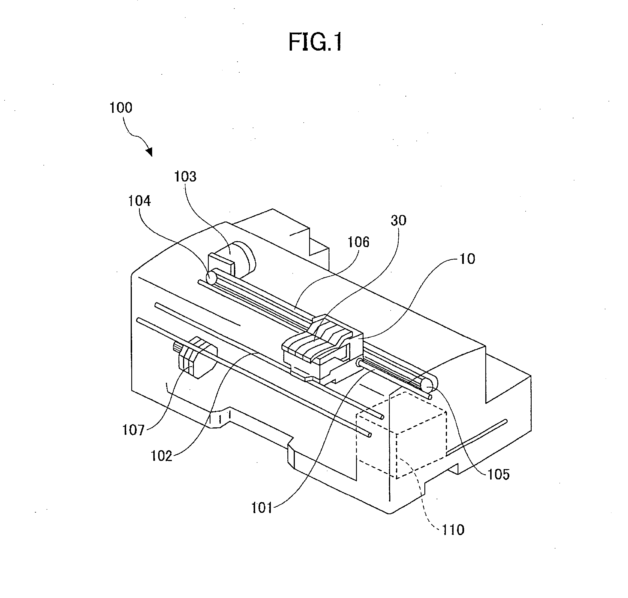
[0028]FIG. 1 is a perspective view schematically showing the internal structure of an inkjet recording apparatus according to an embodiment of the present invention.

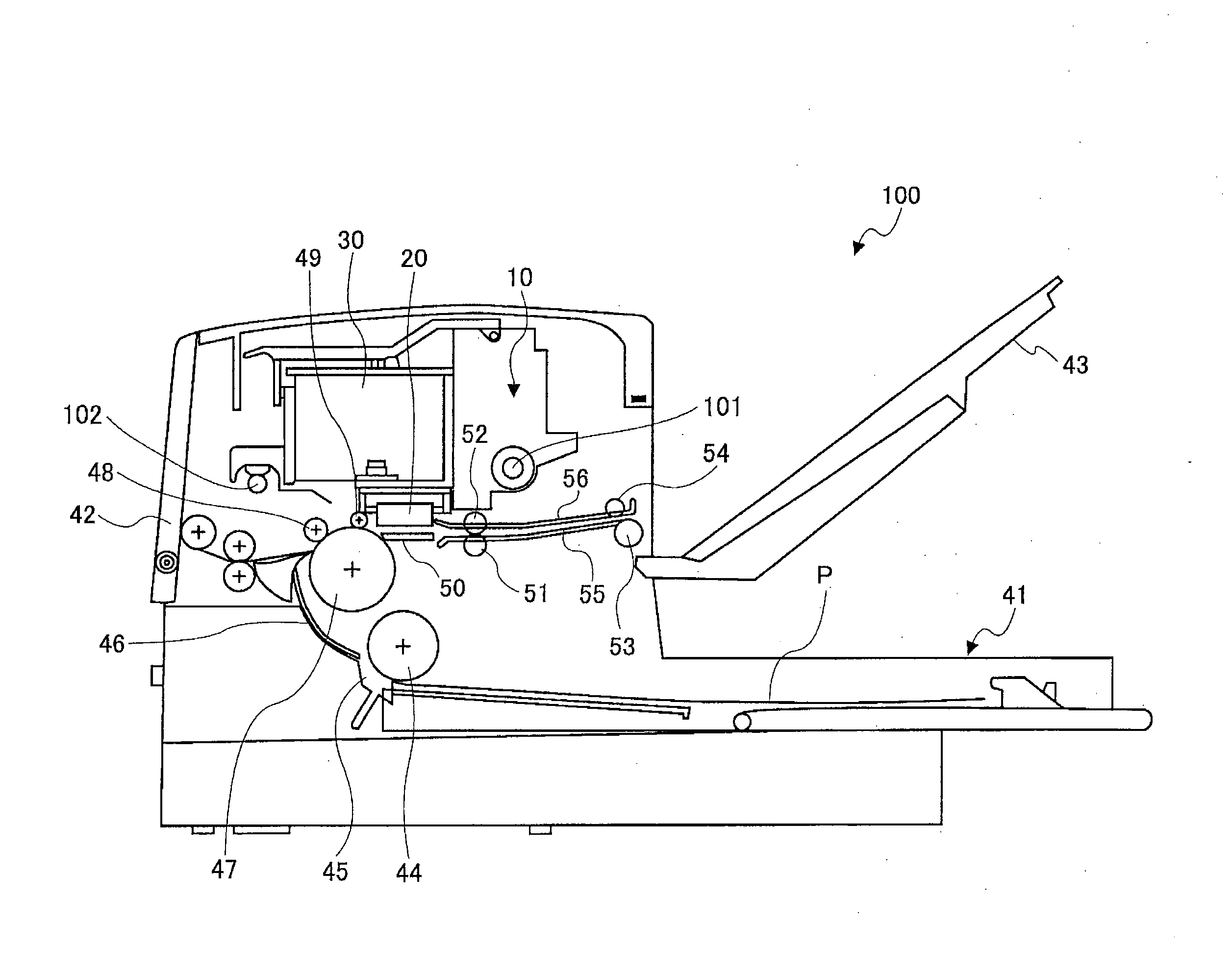
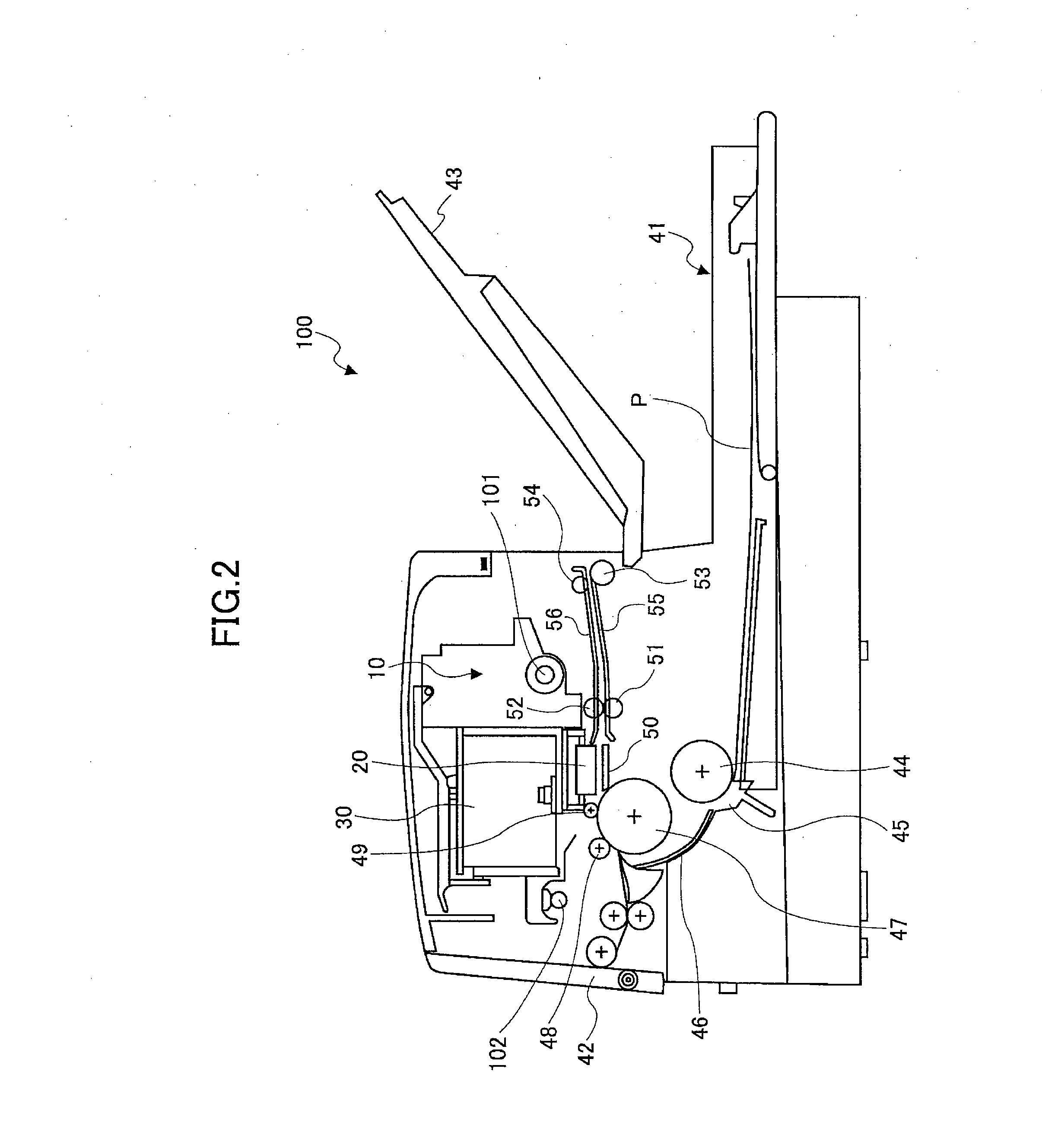
[0029]FIG. 2 is a side view from the sub-scanning direction of the internal structure of the inkjet recording apparatus according to an embodiment of the present invention.

[0030]An inkjet recording apparatus 100 according to an embodiment of the present invention has a carriage 10 that is movable in the main scanning direction, a recording head 20 that is detachably mounted to the carriage 10, and ink cartridges 30 that are mounted to the carriage 10 and are configured to supply ink to the recording head 20. The inkjet recording apparatus 100 has a paper feed cassette 41 (or a paper feed tray) arranged at its bottom side on which multiple sheets of paper (image recording medium) P may be stacked. The...


PUM


Abstract

An inkjet recording apparatus includes a recording head; a carriage to which the recording head is detachably mounted; and a first head protection member that is arranged on the carriage; wherein the recording head is positioned with respect to the carriage in a relative movement direction by moving the recording head relative to the carriage until a first position reference plane of the recording head and a second position reference plane of the carriage come into contact; the first head protection member is arranged at both sides in the relative movement direction of a nozzle face of the recording head and protrudes further than the nozzle face; and the first head protection member is movable with respect to the carriage in the relative movement direction and moves along with the recording head when the recording head moves relative to the carriage.

Description

BACKGROUND OF THE INVENTION[0001]1. Field of the Invention[0002]The present invention generally relates to an inkjet recording apparatus that can be used as an imaging apparatus, such as a printer, a facsimile machine, and a copier.[0003]2. Description of the Related Art[0004]An inkjet recording apparatus can be used in products such as a printer, a facsimile machine, a copier, a plotter, and a multifunction peripheral combining a number of the above functions. An inkjet recording apparatus performs image formation (recording, printing, and imaging are sometimes synonymously used) by having a recording head discharge ink droplets onto an image recording medium. An image recording medium is not limited to paper, and may include OHP, for example. An image recording medium refers to any medium that is capable of having liquid such as ink droplets or solid matter such as toner adhered thereto. It is noted that the terms “recording medium,”“recording paper,” and “recording sheet” may be ...

Claims


Application Information

Patent Timeline
Patent Type & Authority Applications(United States)
IPC IPC(8): B41J23/14
CPCB41J25/34
Inventor NISHIMURA, HIDEAKITAJIMA, YUKITOSHIKATO, MASAKIYAMAGUCHI, KIYOSHI
Owner RICOH KK
Why Eureka
Try Eureka