Visualizing thread state during program debugging

a technology of program debugging and state visualization, applied in the field of visualizing thread state during program debugging, can solve the problems of time-consuming and error-prone process of sifting through tables and lists of values corresponding to the tabl

Inactive Publication Date: 2013-03-21
MICROSOFT TECH LICENSING LLC
View PDF6 Cites 10 Cited by
  • Summary
  • Abstract
  • Description
  • Claims
  • Application Information

AI Technical Summary

Problems solved by technology

As the number of threads increases, the process of sifting through tables and lists of values corresponding becomes more time consuming and error prone.
However, to locate the appropriate debugging information, developers are required to scroll through these lists scanning for anomalous values.

Method used


Image

  • Visualizing thread state during program debugging
  • Visualizing thread state during program debugging
  • Visualizing thread state during program debugging

Examples


Embodiment Construction

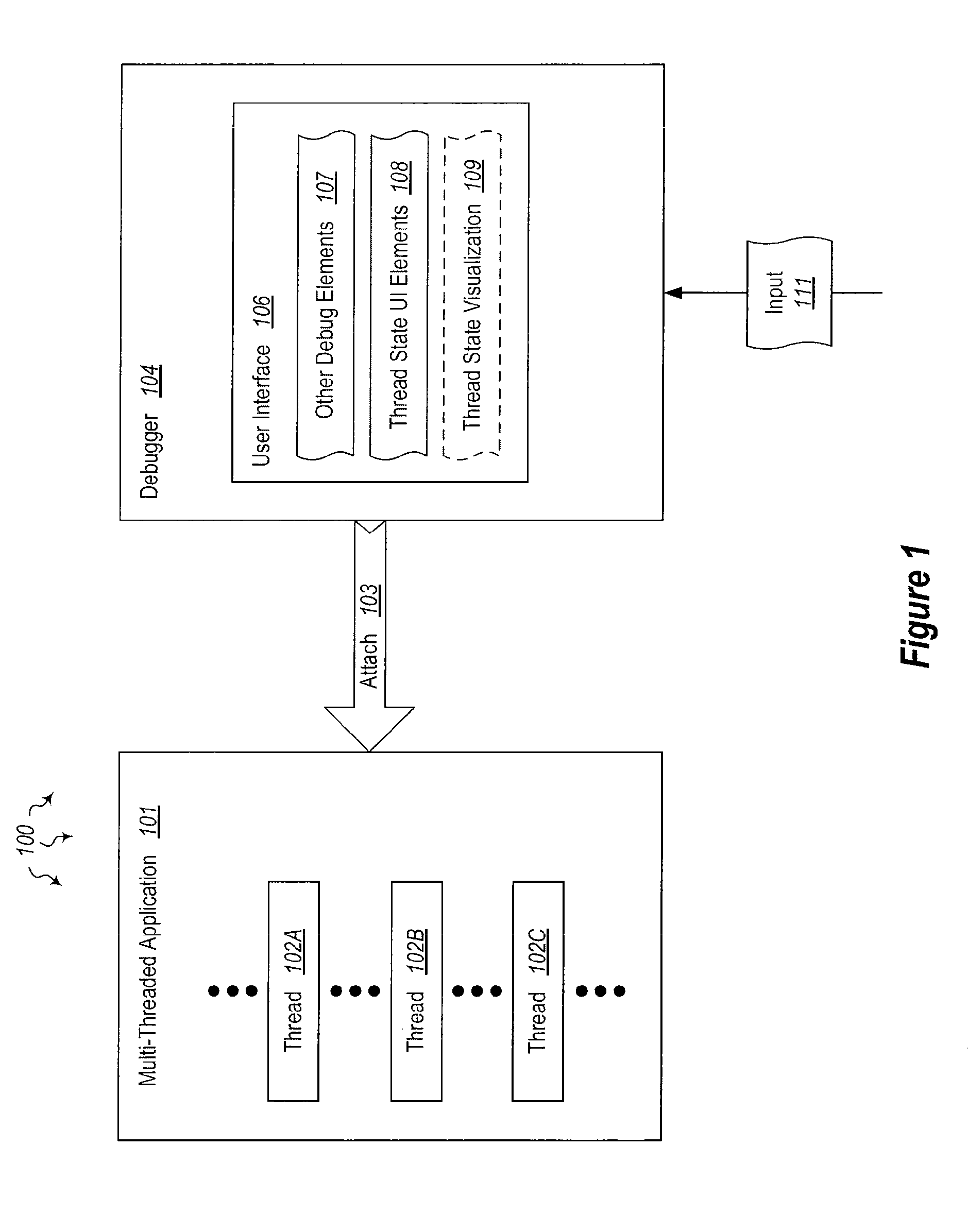
[0017]The present invention extends to methods, systems, and computer program products for visualizing thread state during program debugging. A computer system includes a debugger configured for debugging multi-threaded applications. A visual representation of thread state for a multi-threaded application is provided at a display device.

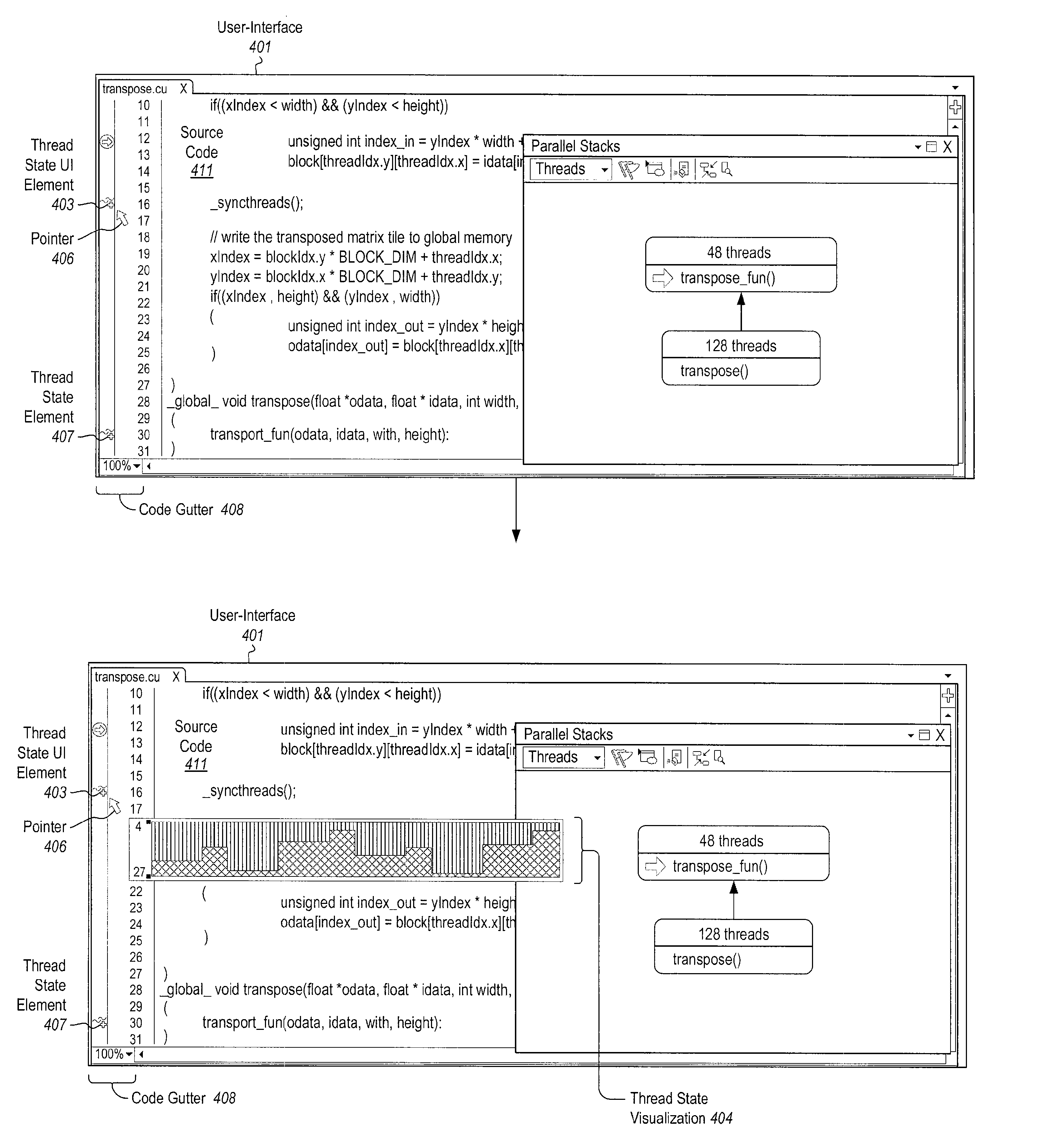
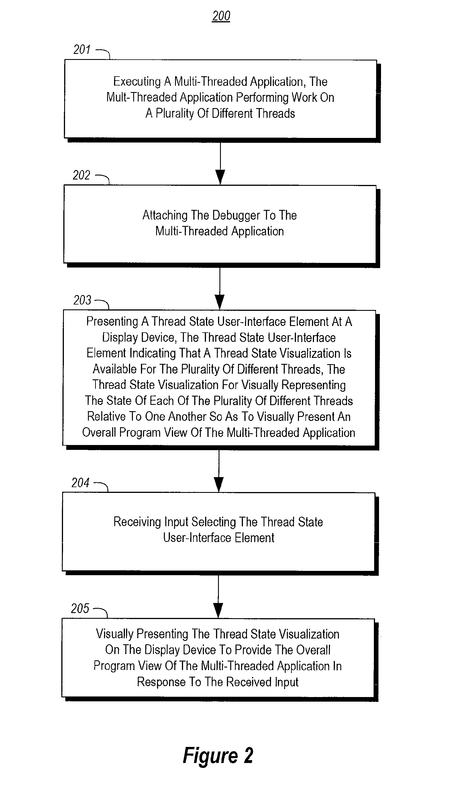
[0018]A multi-threaded application is executed. The multi-threaded application performs work on a plurality of different threads. The debugger is attached to the multi-threaded application. A thread state user-interface element is presented at the display device. The thread state user-interface element indicates that a thread state visualization is available for the plurality of different threads. The thread state visualization is for visually representing the state of each of the plurality of different threads relative to one another. Accordingly, an overall program view of the multi-threaded application can be visually presented.

[0019]Input selecti...


PUM


Abstract

The present invention extends to methods, systems, and computer program products for visualizing thread state during program debugging. A tooltip can present a visual summary of the execution state of the application threads, what the values are, and patterns in the values, during debugging. As such, a developer debugging a parallel application can see the status of threads within a thread block. A visual tooltip (or other presentation mechanism) can be activated by hovering (e.g., placing a mouse pointer) over a user interface element. A visual tooltip can be presented by hovering over a status rollup visualization of the thread states or by hovering over an icon that appears in the code gutter for a code segment. Accordingly, developers can get a concise visual summary of thread states, variables, and values during debugging.

Description

CROSS-REFERENCE TO RELATED APPLICATIONS[0001]The present application claims the benefit of U.S. Provisional Patent Application Ser. No. 61 / 536,474, entitled “VISUALIZING THREAD STATE DURING PROGRAM DEBUGGING”, filed Sep. 19, 2011, which is incorporated by reference herein in its entirety.BACKGROUND[0002]1. Background and Relevant Art[0003]Computer systems and related technology affect many aspects of society. Indeed, the computer system's ability to process information has transformed the way we live and work. Computer systems now commonly perform a host of tasks (e.g., word processing, scheduling, accounting, etc.) that prior to the advent of the computer system were performed manually. More recently, computer systems have been coupled to one another and to other electronic devices to form both wired and wireless computer networks over which the computer systems and other electronic devices can transfer electronic data. Accordingly, the performance of many computing tasks are distr...

Claims


Application Information

Patent Timeline
Patent Type & Authority Applications(United States)
IPC IPC(8): G06F9/44
CPCG06F3/0482G06F11/3664G06F11/3636
Inventor ENGELBECK, GEORGE ESSEXBAPAT, VIKRAMSHARMA, PUNEET
Owner MICROSOFT TECH LICENSING LLC
Why Eureka
Try Eureka