Shared Power System with Multiple Inputs

a power system and input technology, applied in the field of power systems, can solve the problems of low power efficiency, still some difficulties and problems in the related prior art of the power system, and achieve the effect of improving power efficiency and reducing power consumption

a power system and input technology, applied in the field of power systems, can solve the problems of low power efficiency, still some difficulties and problems in the related prior art of the power system, and achieve the effect of improving power efficiency and reducing power consumption

US20130082525A1Inactive Publication Date: 2013-04-04GCCA

Image

  • Shared Power System with Multiple Inputs
  • Shared Power System with Multiple Inputs
  • Shared Power System with Multiple Inputs

Examples


Embodiment Construction

[0017]Some sample embodiments of the invention will now be described in greater detail. Nevertheless, it should be recognized that the present invention can be practiced in a wide range of other embodiments besides those explicitly described, and the scope of the present invention is expressly not limited expect as specified in the accompanying claims.

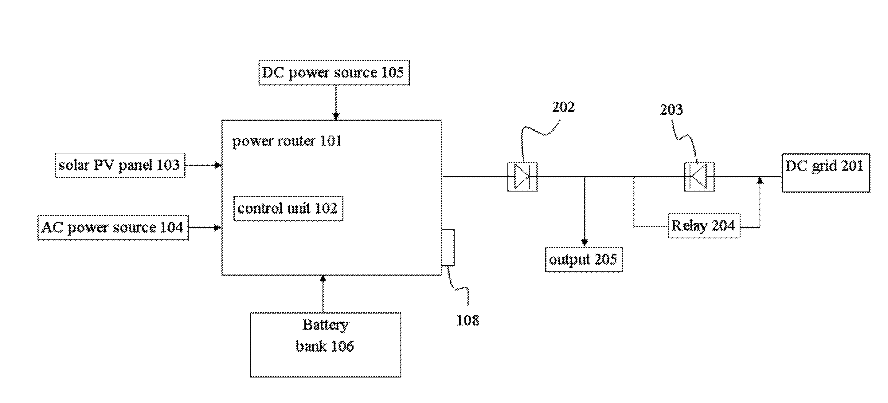
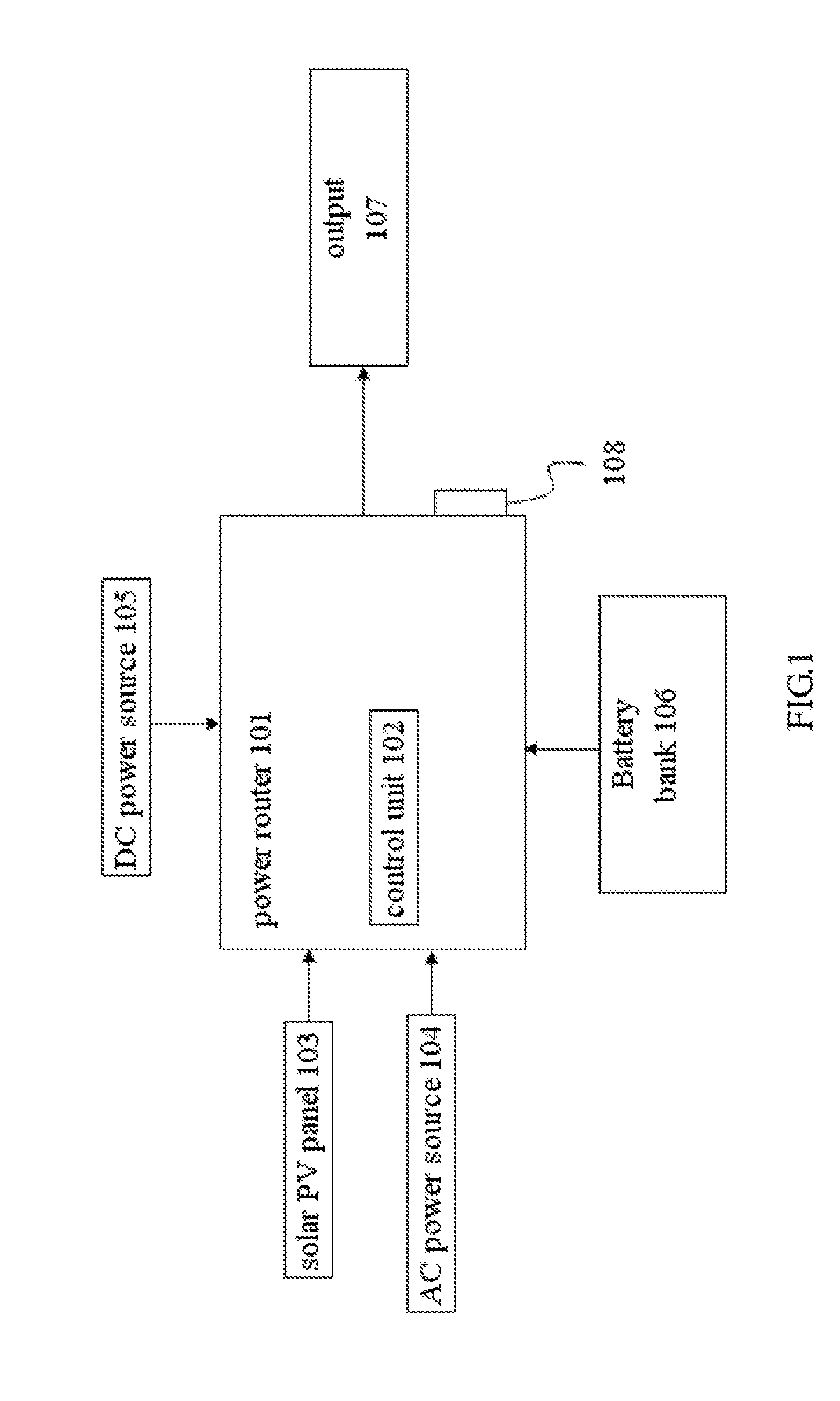
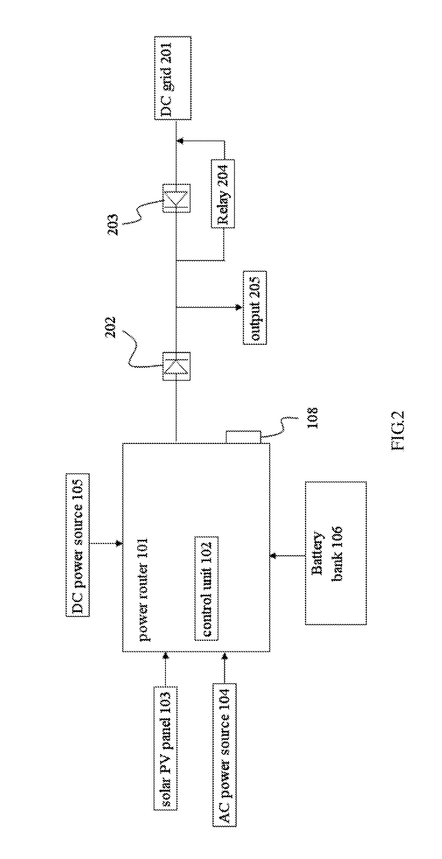
[0018]Referred to FIG. 1, this figure shows one embodiment of the power system with multiple inputs of the present invention. The power router 101 in the present invention has at least five different ports individually connected to a solar photovoltaic panel 103, an AC power source 104, a battery bank 106, a DC power source 105, and a output 107. In this embodiment, the solar photovoltaic panel 103 is coupled to the power router 101 for providing solar energy. The AC power source 104 is coupled to the power router 101 for providing AC power. The DC power source 105 is coupled to the power router 101 for providing DC power. And the outp...


PUM


Abstract

A shared power system includes a power router; a plurality of power input devices respectively connected to the power router; a first diode coupled between the power router and an output; a second diode coupled between a DC grid and the output; wherein the power router can provide power to the output by conducting the first diode when voltage of the power router is higher than the DC grid, and the DC grid can provide power to the output by conducting the second diode when voltage of the DC grid is higher than the power router. The power router can further determine the energy ratio between each power input device to achiever the energy-sharing.

Description

FIELD OF THE INVENTION[0001]The present invention generally relates to a power system, in particular, to a shared power system with multiple inputs.DESCRIPTION OF THE PRIOR ART[0002]Recently, energy-saving and carbon-reducing plays a pretty important role in the industry owning to the global warming Hence, the alternative energy (including solar energy, and wind energy, etc) must be the major power source in the future.[0003]In the prior art, the well-known solar energy systems contains the following types. The first one is the independent power storage system. In this case, the power absorbed by the solar photovoltaic panel can be transferred and stored in the battery bank. If necessary, the stored power can be converted from DC to AC by an inverter, and subsequently transmitted via the wires, and finally converted from AC to DC for applying on ordinary electronic devices. The second one is the feedback-type power system. In this case, the power company can provide commercial power...

Claims


Application Information

Patent Timeline
04 Apr 2013
Publication
US20130082525A1
IPC
H02J1/10; H02J1/00; H02J4/00
CPC
Y02B10/72; H02J9/061; H02J7/35; H02J1/108; Y02B10/70
Inventors
SZU, HSING CHUNG