Steering column cover structure of automotive vehicle

Inactive Publication Date: 2013-04-11
MAZDA MOTOR CORP
View PDF1 Cites 51 Cited by
  • Summary
  • Abstract
  • Description
  • Claims
  • Application Information

AI Technical Summary

Benefits of technology

[0011]An object of the present invention is to provide a steering column cover structure of an automotive vehicle which can properly restrain the foot from mo

Problems solved by technology

Accordingly, there have been problems described below in a vehicle head-on collision.
If the foot Mf slips off the acceleration pedal 104 described above, there may occur some problems in that the foot Mf moves to an inappropriate position for the best impact absorption or a position of the foot Mf becomes abnormal so that some load is applied to the foot Mf improperly.
Specifically, the organ type of pedal, which is different from the hanging type of pedal, has a feature that the

Method used


Image

  • Steering column cover structure of automotive vehicle
  • Steering column cover structure of automotive vehicle
  • Steering column cover structure of automotive vehicle

Examples


Embodiment Construction

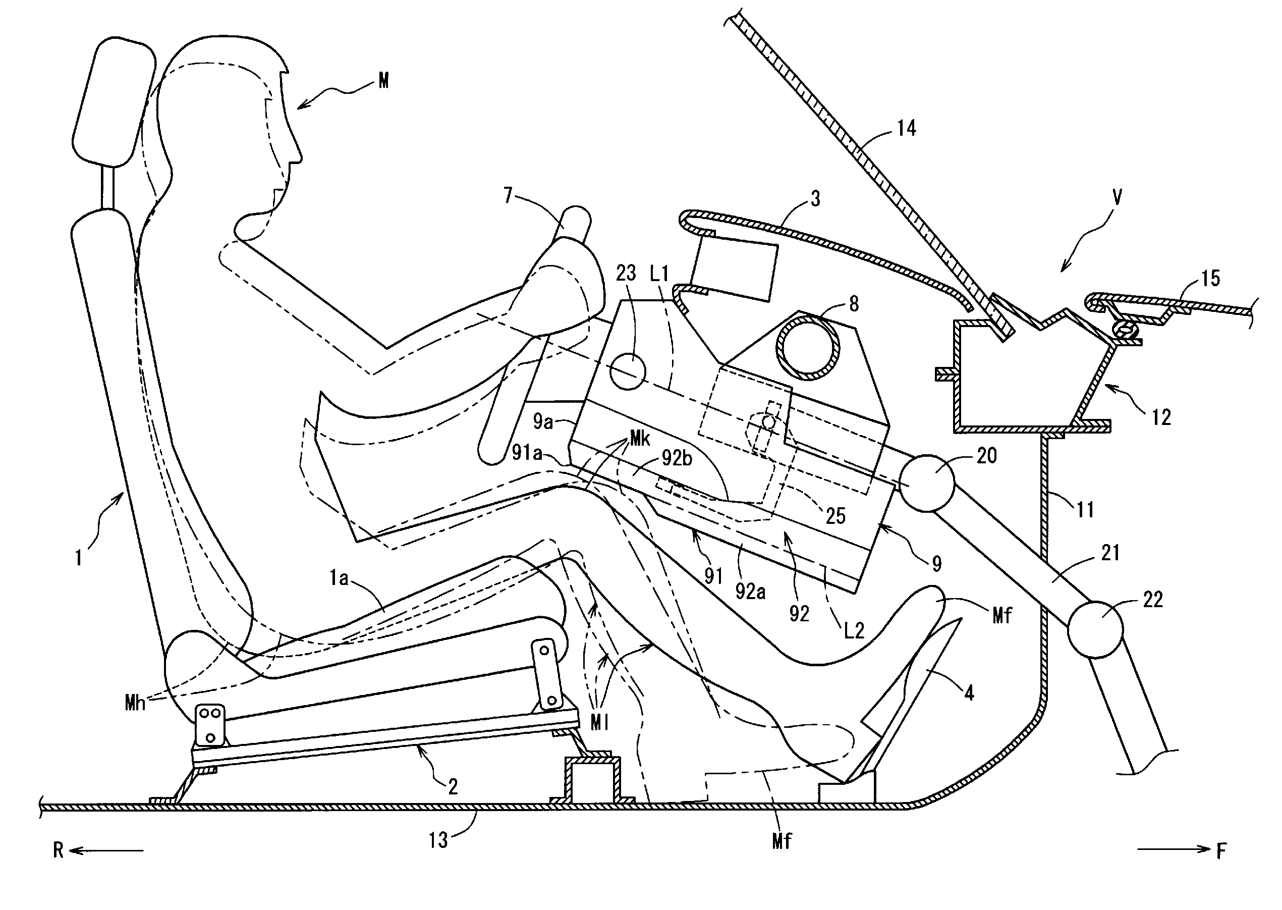
[0032]Hereinafter, preferred embodiments of the present invention will be described referring to the accompanying drawings.

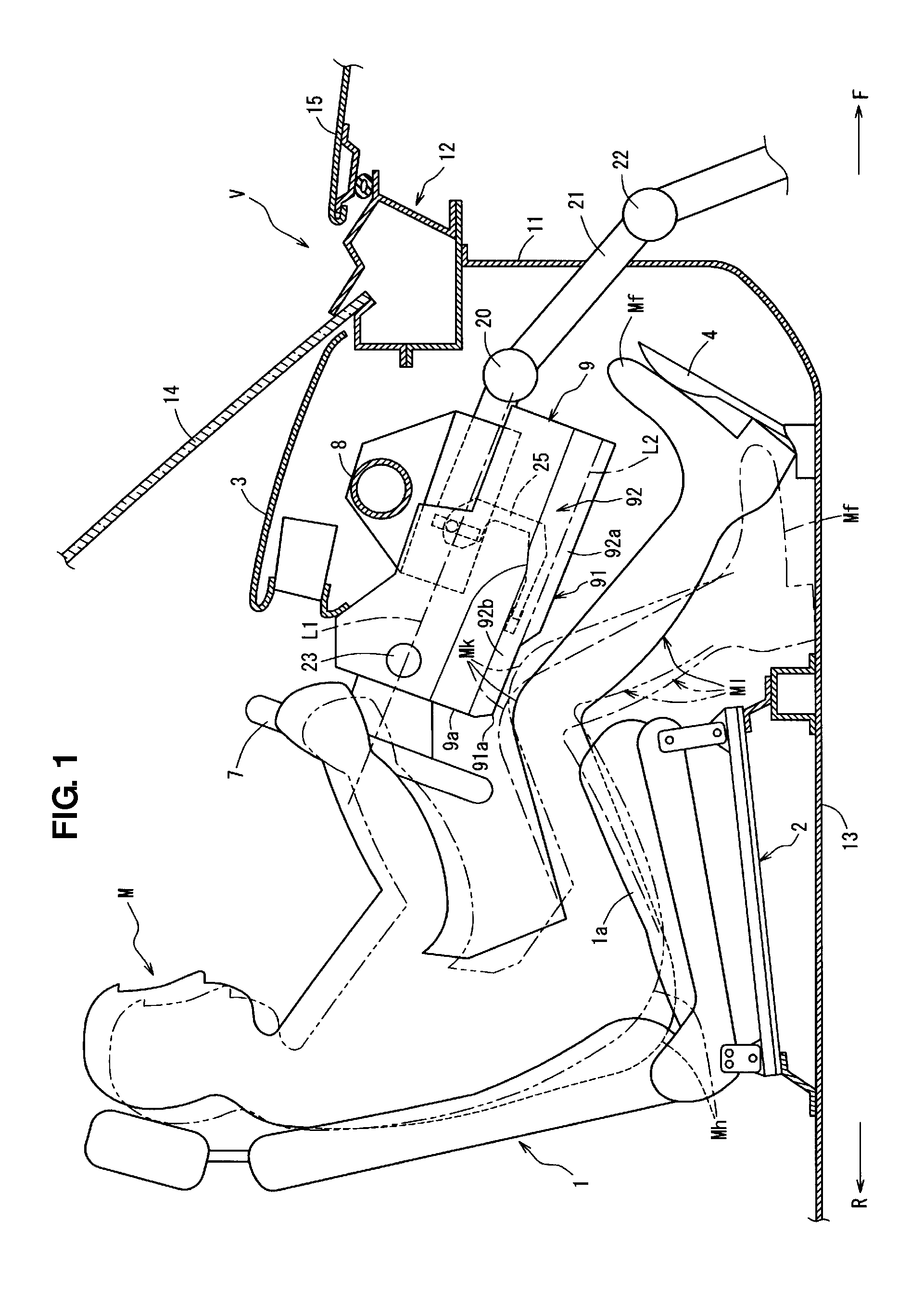
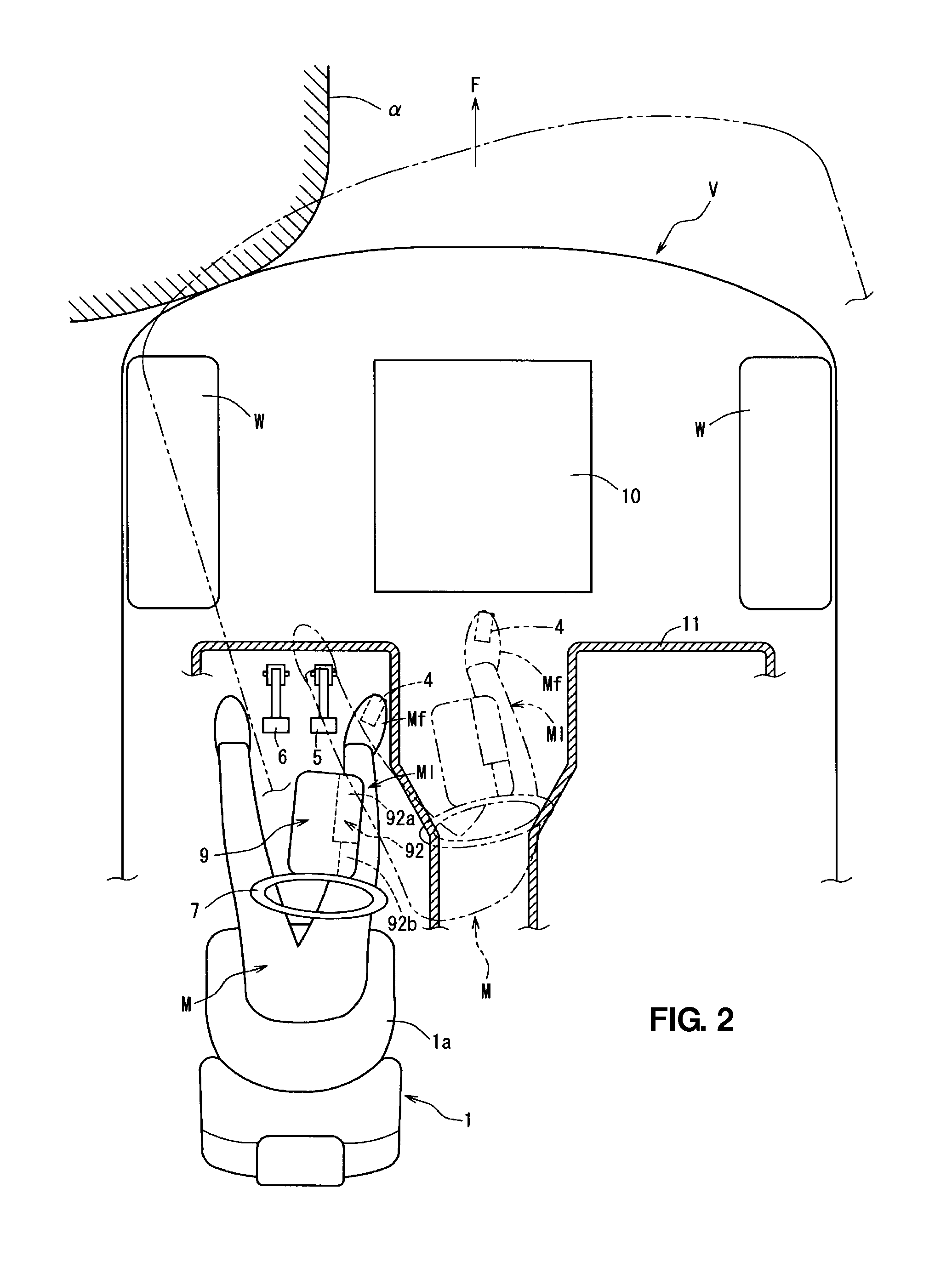
[0033]FIG. 1 is a side view showing a vehicle front portion equipped with a steering column cover structure according to an embodiment of the present invention, and FIG. 2 is a plan view of FIG. 1. In an automotive vehicle V shown in FIGS. 1 and 2, a driver's seat 1 is arranged on the left side in a vehicle compartment, and a longitudinal-position adjusting mechanism 2 to adjust a longitudinal position of a seat cushion 1a of the seat 1 by making it slide is provided. This adjusting mechanism 2 is provided to slant obliquely forward and upward. In the figures, an arrow F shows a vehicle forward direction and an arrow R shows a vehicle rearward direction.

[0034]Further, a resin-made instrument panel 3 which extends in a vehicle width direction is arranged on a front-left side in the vehicle compartment, and below this instrument panel 3 are arranged an acceleratio...


PUM


Abstract

An acceleration pedal is arranged on one side, in a vehicle width direction, of a steering column cover covering a steering column so as to move forward or slant forward through a press operation of a press face thereof. A guide face is provided at a specified portion of a lower face of the steering column cover which is positioned in front of a lower-face rear end portion in a steering-shaft axis direction and on an acceleration-pedal-arrangement side, wherein the guide face is configured to project downward below an extension line extending from the lower-face rear end portion in the steering-shaft axis direction and extend forward. Accordingly, a passenger's foot can be properly restrained from moving, in the vehicle width direction, off the pedal in a vehicle head-on collision, ensuring an appropriate ingress-and-egress performance of a passenger.

Description

BACKGROUND OF THE INVENTION[0001]The present invention relates to a steering column cover structure of an automotive vehicle equipped with a steering column covering a steering column[0002]An acceleration pedal of a pedal device of an automotive vehicle is, differently from a clutch pedal or a brake pedal which are operated with a relatively large press force, required to be operated with a relatively small press force so as to provide a desirable vehicle speed, keeping a press angle of the pedal (press face) properly. Accordingly, there have been problems described below in a vehicle head-on collision.[0003]Specifically, as shown in FIG. 9, when a vehicle V collides against an obstacle α in a vehicle collision, such as an oblique or offset collision, a vehicle body tends to move rotating around the obstacle α as illustrated with a two-dotted broken line in this figure, and a passenger M in a vehicle compartment tends to move in a traveling direction of the vehicle V (prior to the v...

Claims


Application Information

Patent Timeline
IPC IPC(8): B62D1/18B62D1/16
CPCB60R13/02G05G1/30B60K26/02B60R21/05
Inventor OHTSUBO, TOMONORIKUSHIDA, HIROSHITAKEMURA, MASAKIMITSUNARI, TOMOSHITANAKA, MATSUHIRO
Owner MAZDA MOTOR CORP
Why Eureka
Try Eureka