
Medical apparatus and endoscope apparatus

Inactive Publication Date: 2011-03-31
FUJIFILM CORP
View PDF11 Cites 37 Cited by
  • Summary
  • Abstract
  • Description
  • Claims
  • Application Information

AI Technical Summary

Benefits of technology

[0008]An object of the invention is to provide a medical apparatus and an endoscope apparatus capable of performing various types of illumination on an observation area under satisfactory conditions at all times when a general observation using white light and an observation using particular light such as narrow bandwidth of light are performed.
[0021]According to the medical apparatus and the endoscope apparatus, it is possible to perform each of the illumination under satisfactory conditions without causing irregularity of the illumination when the general observation using the white light and the observation using the particular light such as narrow bandwidth of light are performed. For example, it is possible to more appropriately perform a diagnosis or therapy using the endoscope.

Problems solved by technology

However, when the irradiation window emitting the illumination light from the endoscope front end portion is not disposed at an appropriate position with respect to the observation window used for obtaining the image information using an imaging element, the uniform illumination light cannot be emitted from the irradiation window.
In addition, since the positional relationship of the irradiation window in use is different for each of the general observation and the observation using particular light, it is not easy to make both illumination conditions equal to each other.

Method used


Image

  • Medical apparatus and endoscope apparatus
  • Medical apparatus and endoscope apparatus
  • Medical apparatus and endoscope apparatus

Examples


Embodiment Construction

[0037]Hereinafter, an embodiment of the invention will be described with reference to the accompanying drawings.

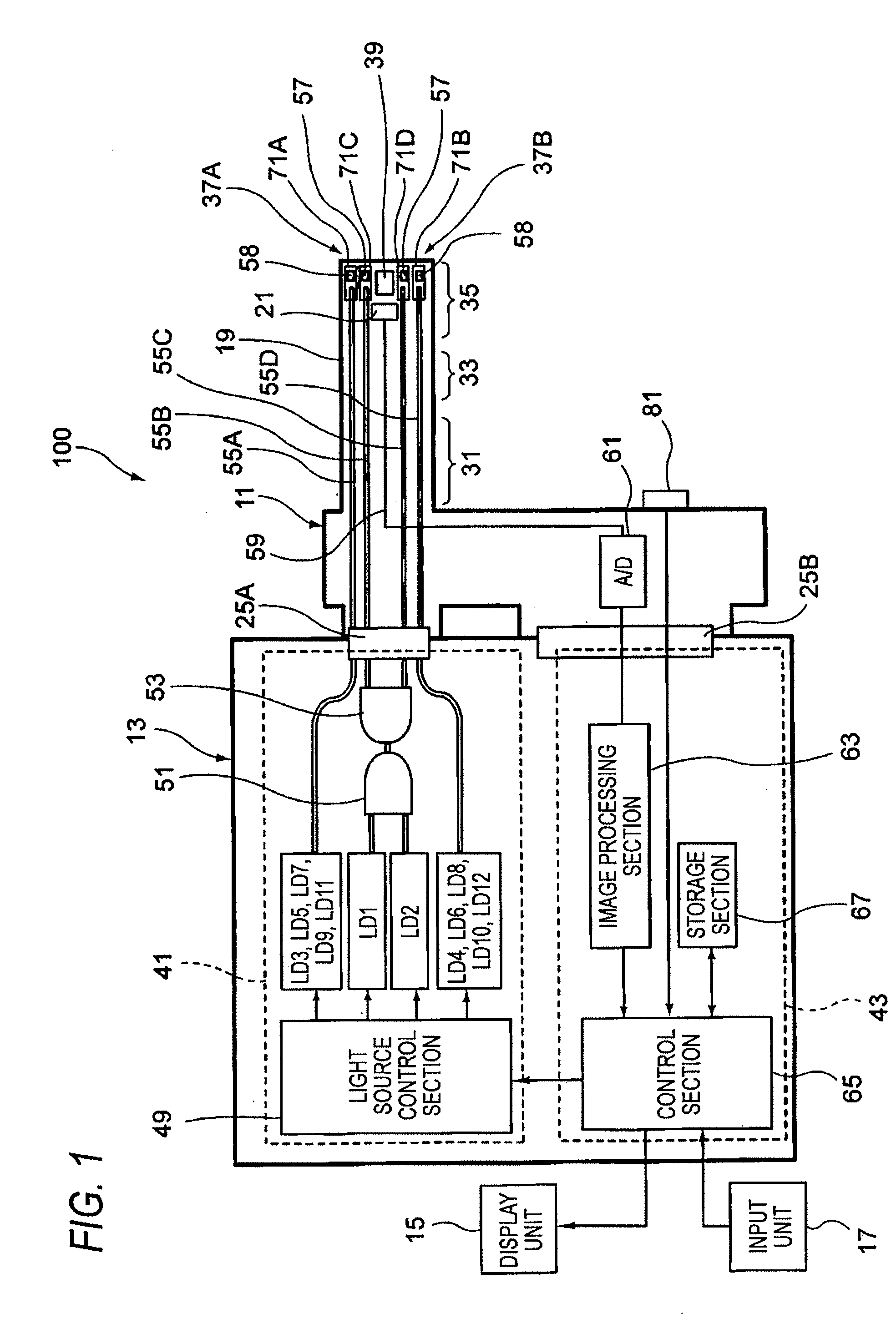
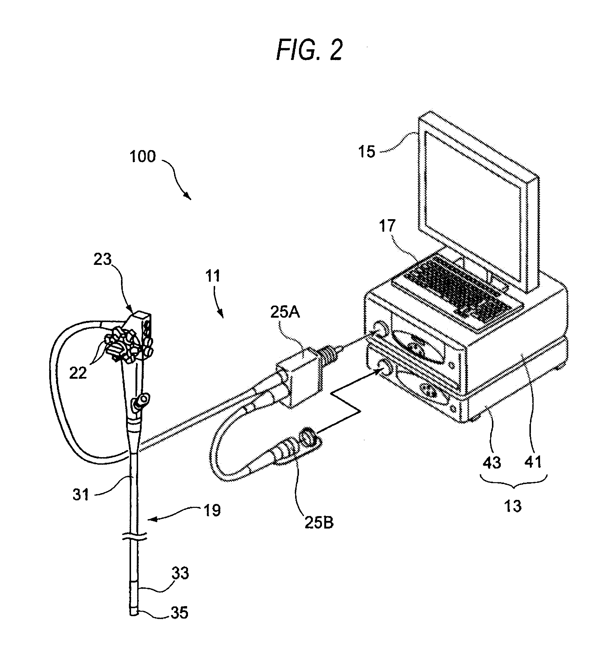
[0038]FIG. 1 is a diagram illustrating an embodiment of the invention, and is a conceptual block diagram of an endoscope apparatus. FIG. 2 is an external view of an example of the endoscope apparatus shown in FIG. 1.

[0039]As shown in FIGS. 1 and 2, an endoscope apparatus 100 as one of medical apparatuses includes an endoscope 11, and a control device 13 to which the endoscope 11 is connected. The control device 13 is connected to a display unit 15 which displays image information or the like, and an input unit 17 which receives an input operation. The endoscope 11 is an electronic endoscope which includes an illumination optical system emitting an illumination light from a front end of an endoscope insertion unit 19 to be inserted into a test object and an imaging optical system including an imaging element 21 (refer to FIG. 1) configured to capture an image of an observat...


PUM


Abstract

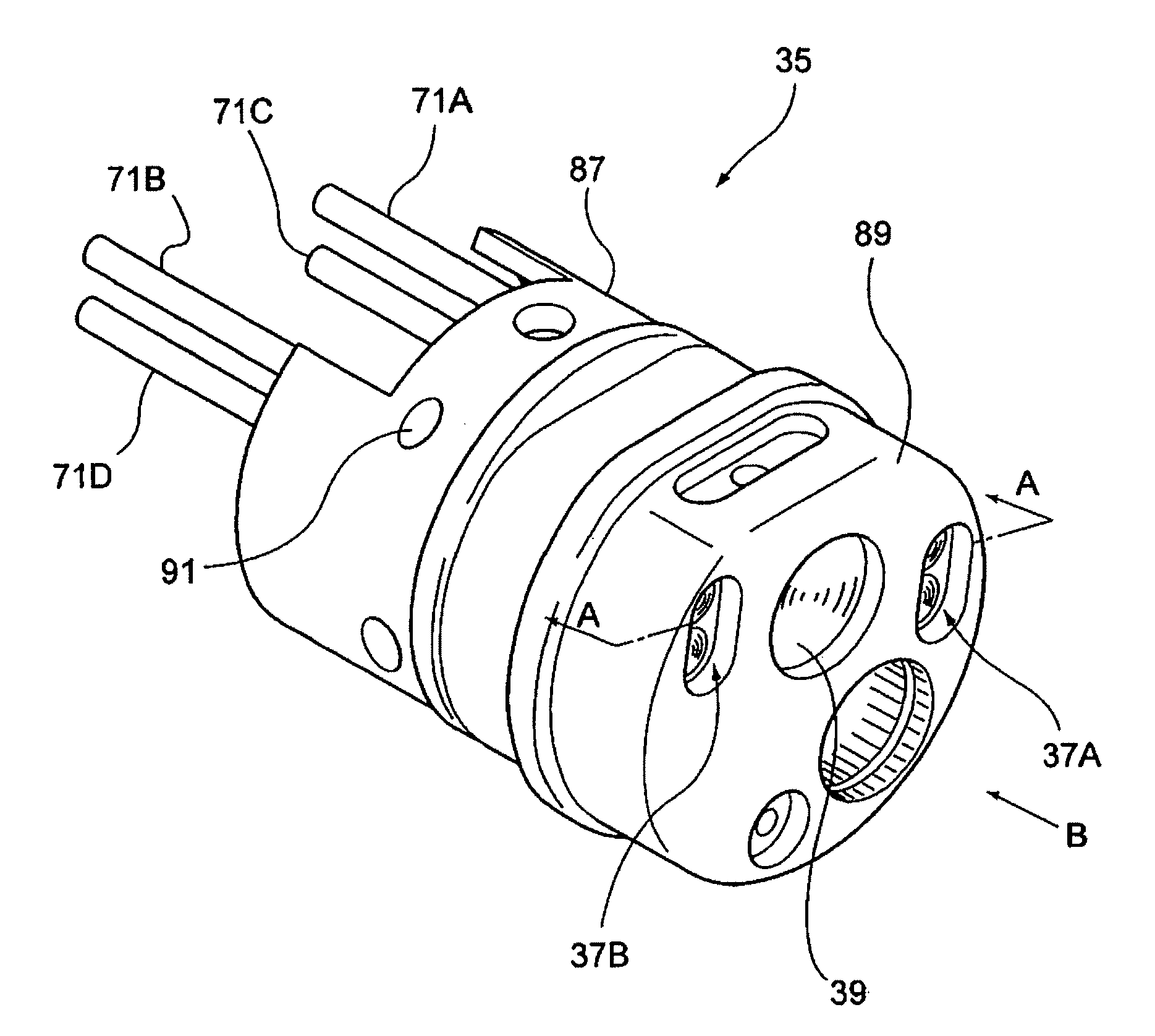
A medical apparatus includes an insertion unit and a light source which supplies light into the insertion unit. A surface of the insertion unit includes: a first and second irradiation portions, a second irradiation portions, and an observation window. wherein each of the first and second irradiation portions has a pair of irradiation windows which emits the light, wherein when a border line bisects a front end surface of the insertion unit through the center point of the observation window, the pair of the irradiation windows are disposed on the both side of the front end surface sandwiching the border line, and wherein a fluorescent body emitting light by the excitation of the light supplied from the light source unit is disposed behind each of optical paths, and the white light is formed by the light supplied to the first irradiation portions and emission in the fluorescent body.

Description

[0001]The present application claims priority from Japanese Patent Application No. 2009-225406 filed on Sep. 29, 2009, Japanese Patent Application No. 2009-296218 filed on Dec. 25, 2009, and Japanese Patent Application No. 2010-148390 filed on Jun. 29, 2010, the entire content of which is incorporated herein by reference.BACKGROUND OF INVENTION[0002]1. Field of the Invention[0003]The present invention relates to a medical apparatus and an endoscope apparatus.[0004]2. Description of the Related Art[0005]Generally, in an endoscope apparatus, an irradiation window and an observation window are disposed at the front end of an endoscope insertion unit, and an observation image is acquired through the observation window by emitting illumination light from the irradiation window. For example, light generated from a white light source such as a xenon lamp is guided to the irradiation window by a light guiding member such as an optical fiber bundle, and is emitted toward an observation area....

Claims


Application Information

Patent Timeline
IPC IPC(8): A61B1/06
CPCA61B1/00096A61B1/0607A61B1/0638A61B1/0653A61B1/063A61B5/0071A61B5/0084A61B5/0086A61B1/0669
Inventor MIZUYOSHI, AKIRAKAGAYA, HIROTOTORII, YUICHIIIDA, TAKAYUKI
Owner FUJIFILM CORP
Learn More