Method and apparatus for determining a color correction matrix by minimizing a color difference maximum or average value

a color correction matrix and maximum or average value technology, applied in the field of color correction matrix determining method and apparatus, can solve the problems of insufficient improvement of light source dependence, inability to completely remove the color tint of light source, and inability to reproduce the color like the skin color observed under sunshin

Inactive Publication Date: 2007-09-04
FUJIFILM CORP +1
View PDF14 Cites 36 Cited by
  • Summary
  • Abstract
  • Description
  • Claims
  • Application Information

AI Technical Summary

Benefits of technology

[0015]The present invention has been made in the light of the aforementioned conventional problems, and a first object of the present invention is to provide color correction matrix determining method and apparatus that are used in a color processing system, in which two color correction matrixes that are a first matrix and a second matrix are provided so that a white balance correction circuit is sandwiched therebetween, and are used to convert image data photographed using a CCD into image data for monitor output that is performed, for instance, in a digital camera. The color correction matrix determining method and apparatus are capable of resolving light source dependency of the second matrix by properly determining the first matrix through the utilization of the characteristic of a construction where two color correction matrixes are provided.

Problems solved by technology

The white balance correction through the gain adjustment gives an appropriate result in many cases, although it is impossible to completely remove the color tint of the light source depending on the kind of the light source.
This results in various problems.
For instance, in the case of a skin tone photographed under a fluorescent lamp, there remains a cyan-green tint even after the white balance correction is performed, so that it is impossible to reproduce a color like the skin color observed under sunshine.
In the color processing system of the conventional digital camera shown in FIG. 9 that uses the two color correction matrixes that are the L-MTX 92 and the C-MTX 98, these color correction matrixes are not produced by sufficiently giving attention to such light source dependency, so that there remains a problem in that the light source dependency of the conventional digital camera is not sufficiently improved.
In a color processing system of such a digital camera, there is also a problem in that its light source dependency is not sufficiently improved.
That is, there is a problem in that there has conventionally been known no special technique of improving the light source dependency described above.
Consequently, there is a problem in that there is not fully utilized a characteristic of the construction where two color correction matrixes are provided in the manner described above.

Method used


Image

  • Method and apparatus for determining a color correction matrix by minimizing a color difference maximum or average value
  • Method and apparatus for determining a color correction matrix by minimizing a color difference maximum or average value
  • Method and apparatus for determining a color correction matrix by minimizing a color difference maximum or average value

Examples


first embodiment

[0099]In the first and second aspects of the present invention, in a color processing system shown in FIG. 9 of a digital camera or the like in which two color correction matrixes (a first matrix (L-MTX) and a second matrix (C-MTX)) are provided so that a white balance correction circuit is sandwiched therebetween, the first matrix is properly determined so that there is resolved a light source dependency of the second matrix. Note that in FIG. 9, a γ circuit is arranged so as to precede the second matrix, although there is imposed no specific limitation on this arrangement order and there occurs no problem so long as the first matrix and the second matrix are arranged so that the white balance correction circuit is sandwiched therebetween.

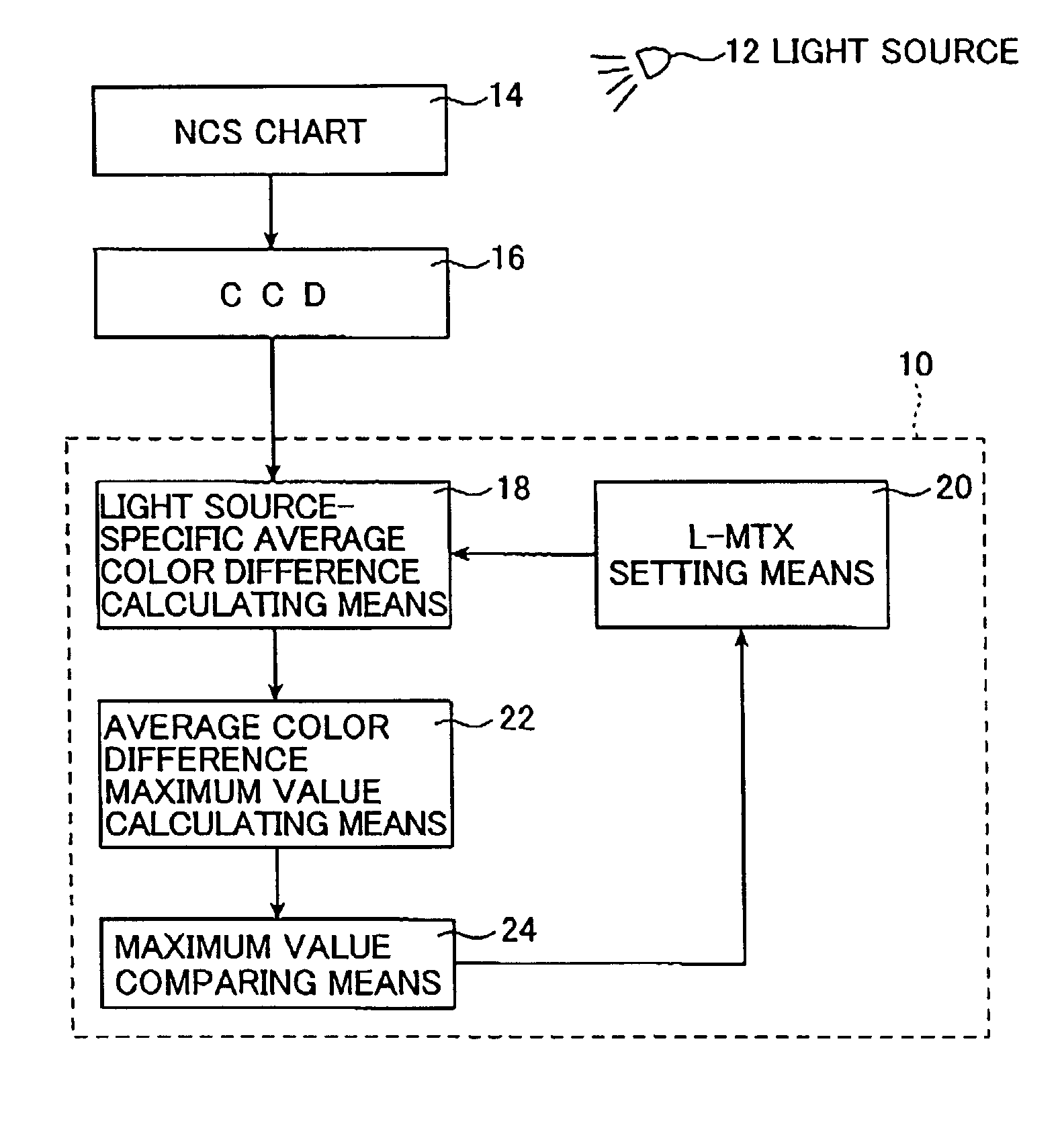
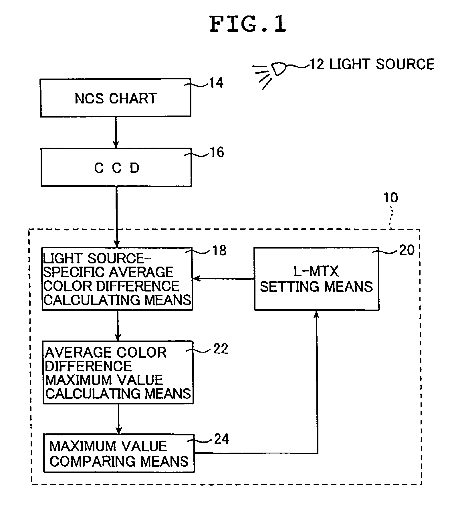
[0100]FIG. 1 is a block diagram showing an outline of a construction of a color correction matrix determining apparatus according to the first embodiment of the second aspect of the present invention that carries out a color correction matrix dete...

second embodiment

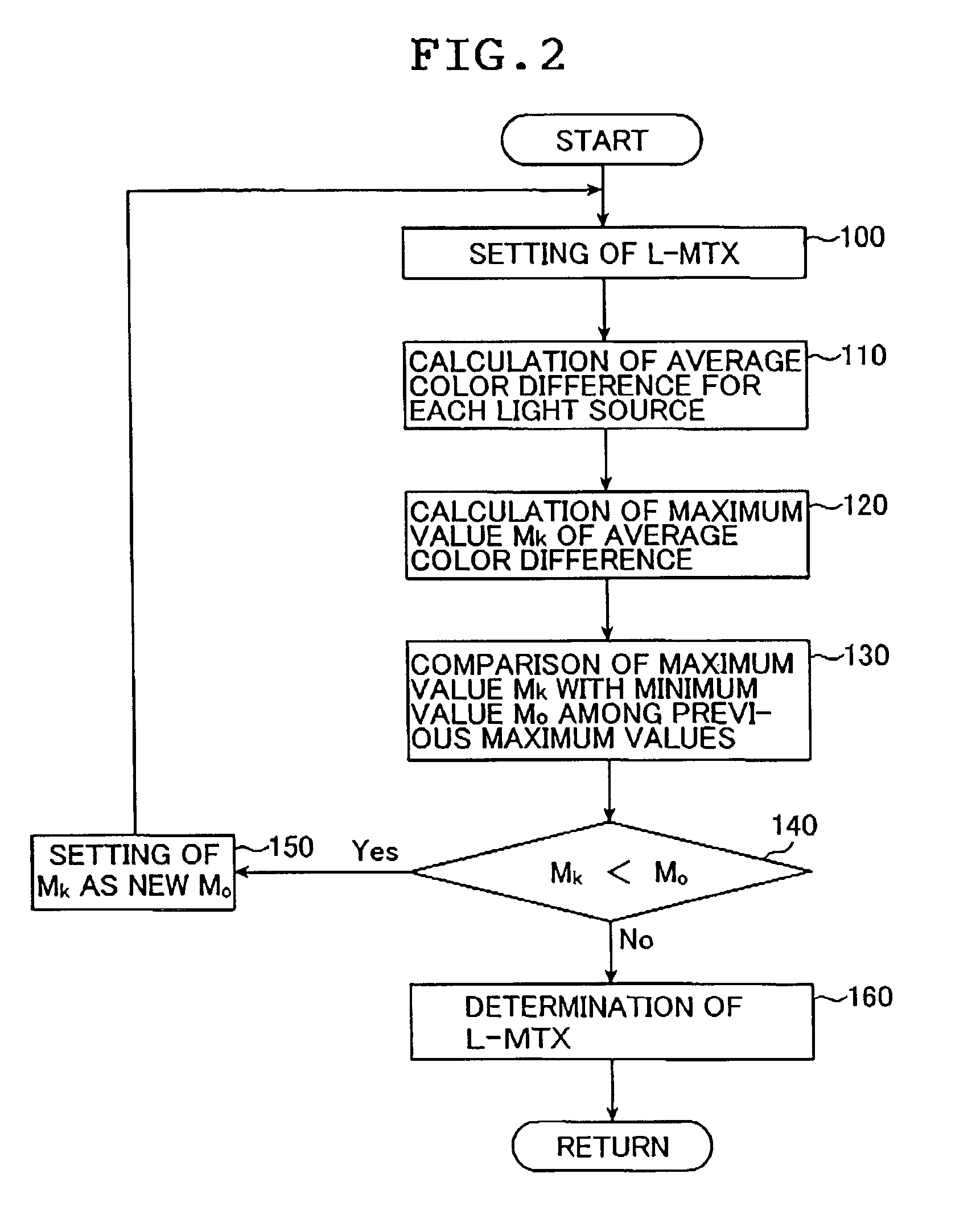
[0116]Next, there will be described the present invention.

[0117]In the first embodiment described above, in order to determine the first matrix, the first matrix is optimized by minimizing the maximum value of the average color differences for respective light sources. In this embodiment, however, the first matrix is optimized by minimizing an average value of the average color differences for respective light sources.

[0118]FIG. 3 shows an outline of a construction of a color correction matrix determining apparatus 30 of this embodiment.

[0119]As shown in FIG. 3, the color correction matrix determining apparatus 30 of this embodiment inputs image data obtained by imaging the NCS chart 14 as a subject using the CCD 16 under the light source 12, and includes an average color difference calculating means 32 for calculating an average color difference for each light source from this image data, a first matrix (L-MTX) setting means 34, an average color difference average value calculating...


PUM


Abstract

Color correction matrix determining method and apparatus and image photographing method and apparatus are used in a color processing system that converts input image data into output image data and has two color correction matrixes that are a first matrix and a second matrix, with a white balance correction circuit being sandwiched between the first matrix and the second matrix. The color correction matrix determining method and apparatus input a light source range and determines the first matrix based on this inputted light source range on the occasion of determining the color correction matrix in the color processing system. The image photographing method and apparatus discriminates a photographing light source range and determines the first matrix based on the discriminated photographing light source range.

Description

BACKGROUND OF THE INVENTION[0001]1. Field of the Invention[0002]The present invention relates to color correction matrix determining method and apparatus and image photographing method and apparatus using the color correction matrix determining method and apparatus. In particular, the present invention relates to a correction matrix determining method and apparatus that determine a color correction matrix used to perform image conversion in a color image photographing system such as a digital camera. The present invention also relates to image photographing method and apparatus that improve light source dependency in a color processing system of the image photographing apparatus that converts input image data, such as image data obtained through photographing with a CCD, into output image data such as image data for display on a monitor.[0003]2. Description of the Related Art[0004]In usual cases, in a color image photographing system such as a digital camera, a scene to be photograp...

Claims


Application Information

Patent Timeline
Patent Type & Authority Patents(United States)
IPC IPC(8): H04N5/228G06K15/00G06K9/00H04N9/73
CPCH04N9/735H04N23/88
Inventor NOGUCHI, TAKAFUMI
Owner FUJIFILM CORP
Why Eureka
Try Eureka