
High pressure discharge lamp lighting device

a technology of lighting device and discharge lamp, which is applied in the direction of gas discharge lamp usage, climate sustainability, light sources, etc., can solve the problems of unstable discharge position, uneven tip end surface of the electrode, and forming of projections, so as to prolong the life of the light source, reduce the generation of flicker, and good balance

Active Publication Date: 2012-12-13
USHIO DENKI KK
View PDF8 Cites 18 Cited by
  • Summary
  • Abstract
  • Description
  • Claims
  • Application Information

AI Technical Summary

Benefits of technology

[0023]The low frequency of the cathode cycle is supplied consecutively, but because the current with the basic frequency is supplied periodically, the temperature of the electrode does not decrease too much. By means of suitably changing the polarity of the electrode being supplied with the current having the low cycle frequency, it is possible to maintain the evaporation of tungsten and the build-up mode at both electrodes with a good balance, to maintain the shape of the projections (electrodes) optimally and to extend the lifetime of the light source.
[0037](4) By controlling a lighting device lighting a high pressure discharge lamp wherein mercury is enclosed and a pair of electrodes is disposed opposite each other in the discharge vessel such that the period of the supply of the basic frequency gradually increases and decreases with each specified time, a time period during which tungsten melts in a wide range and a time period during which there is no such melting can be created alternatingly, the shape of the projections of the electrodes can be kept optimally and the lifetime of the light source can be extended.

Problems solved by technology

Now, if a high pressure discharge lamp remains lit in the same condition for a long time, a plurality of projections are formed and the tip end surface part of the electrodes may become uneven.
It is known that, if the surface part of the electrode tip end is uneven, the discharge position becomes unstable and a reduction in brightness and flicker due to the movement of the arc.
However, because the technique described in this patent publication constantly increases and decreases the frequency, over the course of time, there is the practical problem that an annoying noise is generated.
However, with this technique, it is not possible to prevent brightness changes resulting from the power changes.

Method used


Image

  • High pressure discharge lamp lighting device
  • High pressure discharge lamp lighting device
  • High pressure discharge lamp lighting device

Examples


embodiment 1

[0194]The Number of Times that Generation of the Basic Frequency Becomes 0

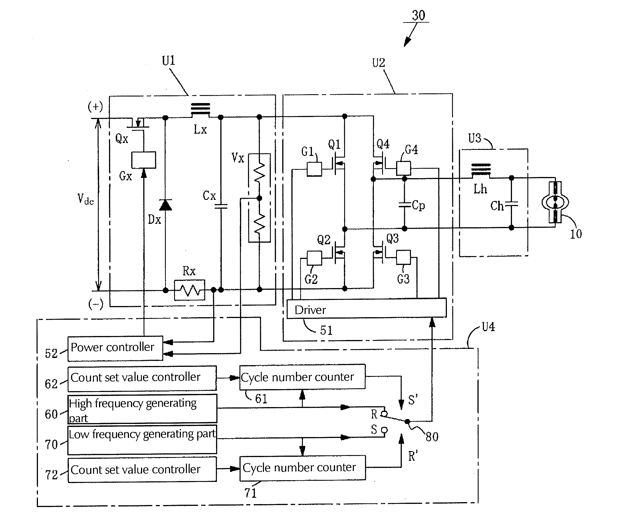
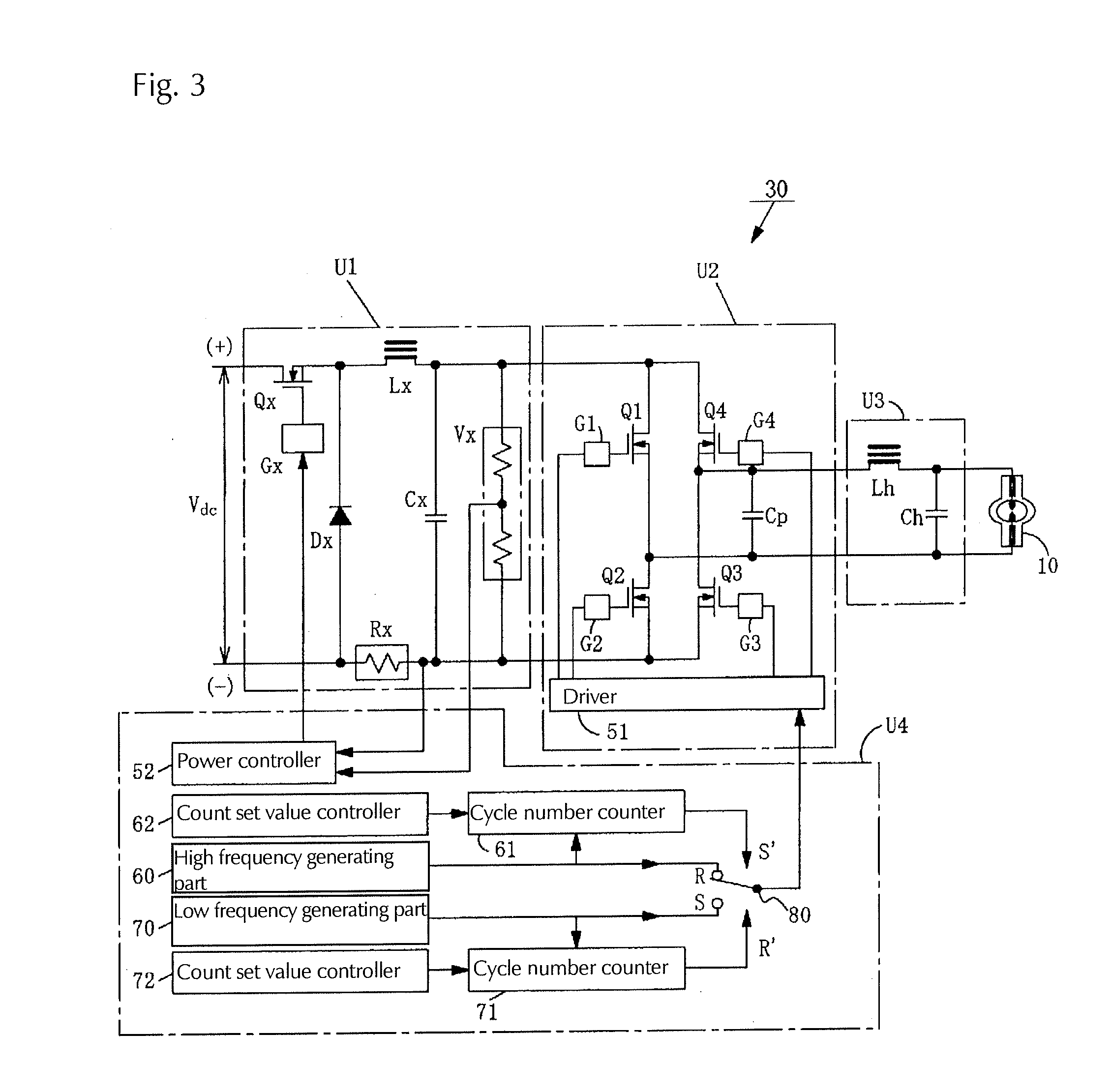
[0195]FIG. 9 shows an example of the waveform of the lamp current supplied to the high pressure discharge lamp 10 from the supply device 30, wherein the vertical axis represents the current value and the horizontal axis expresses the time. FIG. 10 is a view explaining the state of the change of the set value for the number of cycles used to control this current waveform, wherein the vertical axis represents the number of cycles (times) the basic frequency is generated and the horizontal axis expresses the time.

[0196]When the time changes like ta, tb, tc, td, . . . such as in FIG. 10, and the set value of the number of cycles changes, the current waveform appears in the sequence (a)→(b)→(c)→(d), such as shown in FIG. 9. When afterwards the time becomes tc', tb', ta' after td, there is the change of (d)→(c)→(b)→(a) in FIG. 9.

[0197]The example shown in FIG. 9(a) is the case of the largest number of cycles of the ...


PUM


Abstract

To maintain the shape of the projection on the electrodes of the tip end for a long time to extend the lifetime of a discharge lamp, a lighting device lighting a high pressure discharge lamp supplies alternating current such that an alternating current with a basic frequency at the time of the steady state lighting selected from a range between 60 and 1000 Hz and a low frequency of a half cycle with a frequency lower than the basic frequency are generated alternatingly. The alternating current is supplied such that the waveform with one polarity of the low frequency appears consecutively at least twice. It is also possible for the alternately generated low frequency to be lower than the basic frequency in a range from 5 to 200 Hz, and for the interval during which the basic frequency is supplied to be gradually increased and decreased at specified times.

Description

BACKGROUND OF THE INVENTION[0001]1. Field of the Invention[0002]This invention relates to a high pressure discharge lamp lighting device comprising a super high pressure discharge lamp optimally used as the light source for a projector, etc. and a power supply device.[0003]2. Description of Related Art[0004]Lamps used as the light source of a projector, etc., are super high pressure discharge lamps where at least 0.2 mg / mm3 of mercury is enclosed in the interior of the discharge vessel and the pressure at the time of the lighting reaches at least 200 atm are utilized. It is known that, in such lamps, a projection is formed at the surface of the tip end of the electrodes when the lamp is lit and a stable lighting condition is maintained by holding the arc at these projections.[0005]Now, if a high pressure discharge lamp remains lit in the same condition for a long time, a plurality of projections are formed and the tip end surface part of the electrodes may become uneven. It is known...

Claims


Application Information

Patent Timeline
Patent Type & Authority Applications(United States)
IPC IPC(8): H05B41/36
CPCH05B41/2888Y02B20/208H05B41/2928Y02B20/00
Inventor IMAMURA, ATSUSHISAMEJIMA, TAKANORI
Owner USHIO DENKI KK
Learn More