Generation of one or more edges of luminosity to form three-dimensional models of objects

a technology of luminosity and edges, applied in the field of scanning devices, can solve the problems of not being well suited to apply to a wide range of applications, scanners are expensive, and the diagram system b>100/b> may not be well suited to model 3d imagery for three-dimensional objects

Active Publication Date: 2020-02-06
ADVANCED SCANNERS INC
View PDF0 Cites 19 Cited by
  • Summary
  • Abstract
  • Description
  • Claims
  • Application Information

AI Technical Summary

Benefits of technology

[0235]The advantages of the present invention include, without limitation, that the light sources of the present invention involve a minimum of optics, which incur weight and expense, and include the possibility of no lenses, in order to project a sharply contrasted pattern onto the object being scanned; that it does not require optics to optimize a beam of light at a particular distance; that the light sources of the present are relatively inexpensive compared to other technologies, such as lasers; that the light sources of the present invention are well-suited for a large depth of field; that the light sources of the present invention may comprise very bright sources and preserve accuracy if they are far away enough from the shadow caster; that the light sources of the present invention do not rely on a pulsing technology, or phase-detection technology used in schemes that assess distance through time-delay measurements, which may limit the number of simultaneous points measured, as well as the absolute resolution that is limited to the rise-time of typical electronics (100 ps), implying a 0.6-inch resolution in depth (meaning a 0.6 inch change results in an approximately 100 ps delay), and which are sensitive to noise; that the light sources of the present invention may optimally be an “extended” source along one dimension, in other words, a line, which illuminates the object from more angles than competing technology, and, as three-dimensional-scanned surfaces must be simultaneously illuminated and observed, this greater angle of illumination is advantageous, as more of the object can be scanned than typical projection-based scanners; that the hardware of the present invention can be separated among all three elements: light source, shadow caster, and light receiver, and, as such, there can be multiple cameras looking at a single shadow edge from one or more shadow casters; that, because a “point-source” that has a practical width, an extension of such a source, by reproducing it along a line, adds light while improving the scene contrast because the extension adds light, but does so with a reduced “solid angle” of the point light source because it is further away from the edge of the shadow caster, so the linear light source adds brightness while improving the resolution of the light source, on average; that the extended light source does not need to be not contiguous, and there may be more than one light source, as long as they are co-linear; that the light sources of the present invention can all conspire to cast one shadow edge (and, indeed increase its contrast), as this conspiring extends the range of angles while using separate light sources of practical construction, and increases the potential for developing custom illumination geometries for a given task; that a single light source can be used by multiple shadow casters, if they are removed physically from the light, and a single long and bright light at the top of a room can be used more locally by shadow caster-camera systems throughout that room, if they are aligned; that the shadow generation scheme of the present invention can produce large depth-of-field shadows, which retain their sharpness due to a geometric effect, and not an effect caused by lenses, which inherently introduce depth-of field issues, such as with projectors that use lenses, which must be tailored to produce sharp patterns only over a limited range; that, by removing the necessity of an engineered projector, and by removing the specificity of laser single-wavelength operation, the light source of the present invention can be of any wavelength, broad or narrow bandwidth, and use white-light, and a fluorescence-excitation wavelength, in the same scan and use a single camera in alternating “modes;” that the present invention may also use laser light to cast a shadow or cast a shadow into laser-light, which is particularly advantageous for fluorescence measurements during surgery; that, as a matter of spatial resolution, white light used in the present invention has less visible diffraction artifacts, producing a sharper shadow, than does laser light and white light does not suffer the problem of speckle as much as narrow-band laser light does, and this noise source is avoided by the present invention; that the sharp edge, and the large contrast afforded by the shadow in the present invention with its simple single-line geometry allows subsurface scattering measurements to be made on the fly, leading to real-time biomedical applications, such as optical biopsy for detecting skin cancer or cancer surgeries, since determining the margins of healthy versus cancerous tissue is an ongoing challenge; that, in the field of security, these subsurface scattering measurements allow for improved security scanning because it is very difficult to fake subsurface scattering features of a face; that the present invention; that these subsurface scattering measurements are useful to the cosmetics world in computer graphics recreation of actors' faces; that the use of white-light is advantageous over single-frequency sources (laser or lamp) because real-time comparisons of scattering properties may be made for different frequencies of light, such as the blue versus red, for example; that with the present invention it would be possible to use two distinct frequencies, since an array of LEDs may be used, and LEDs of different wavelengths may be interwoven and flash alternately, with the camera optimized in its exposure on each alternate frame to capture the color information; that the side triangle cross sections of the shadow casters of the present invention allow light to be extended laterally, while enabling the application of a shadow-caster very close to the object, while projecting a single, contiguous shadow edge, and these side shadow casters can connect to an intermediate shadow caster, as long as the shadow caster components, together, make a triangular cross-section as viewed along the line as defined by the extended light source; that the segmented shadow casters can speed up scans scalably for object geometries without much complexity by adding additional bands of shadows, so that, during the sweep, for simple objects, these separate shadows will not appear overlapping, and can be independently analyzed with the separation of the shadows depending on the complexity of the object; that the simplicity of the light source of the present invention indicates that any linear light source could serve, including x-rays, with which lensless projection of shadows is relatively easy, although X-ray structured scanning would not usually be particularly feasible, as it usually requires imaging a pattern to the object, and then imaging the scattered light; that typical embodiments of this technology hold the camera and the light source still for improved accuracy with the changes to the scene being due primarily to the shadow edge, meaning that overall the illumination of the object changes very little during the scan, especially for shadow areas that are relatively narrow, allowing for a large signal-to-noise ratio in the generated scan; that typical embodiments of the present invention have the camera, light, and shadow caster, all robustly attached to each other in a pre-calibrated way, so that of there is a loss of calibration, it can be determined again in an autonomous way (albeit with additional hardware such as a calibration stand); that the scanning technology of the present invention may be configured with a variety of tradeoffs including brightness versus accuracy, so that flat items can be scanned with very fine resolution (microscopy), using a specific optimized geometry; that the present invention has improved potential raw accuracy; that large-scale items can be measured with sub-mm accuracy, as long as cameras record the shadow edge; that the shadow can always be made sharp for improved accuracy, if it can be brought close to the item being scanned; that the scanner does not depend on feature-matching, or photogrammetry, in any way and instead depends on triangulation alone, using the aforementioned high signal to noise ratio, providing a single “right” answer, and increasing the certainty of the scan; that the noise in a scan can often be removed in a more automated way than other scanning techniques, which are often marred by banding and other artifacts; that with the present invention there are occasions when noise in the image overwhelms even the contrast afforded by the sharp shadow edge, however, this noise usually takes place many pixels from the shadow edge, and in the triangulation of the data that follows, then, such noise points end up very far removed and sparsely positioned in 3D space, making them easily filtered using a density-threshold algorithm, which calculates the average radius of each point from a certain number of its closest neighbors, and removes those with an average distance greater than a threshold, g resulting in a very clean scan; that object motion may be more easily compensated with the present invention by tracking motion during the scan (perhaps with a separate camera); that the present invention is useful for scanning people, who tend to shift their weight side-to-side, especially when sitting; that the present invention detects for each picture both the color of the object and its 3D coordinate simultaneously, meaning that if the object moves in three dimensions, its accurate color will also be represented, and the simultaneous determination of three dimensional shape, as well as color, is on a pixel-by-pixel basis removes the complex problem of registering the color image on a 3D scan in general, and in the present invention this data is auto-aligned, as it comes from a single camera. Overall, the present invention offers improved scanning quality and accuracy, which is relatively inexpensive, in the generation of three-dimensional models using shadow casters.

Problems solved by technology

While traditional structured-light scanner systems are functional, they are not well suited to apply to a wide range of applications because these systems typically require materials and resources that make the scanners cost prohibitive.
While the scanner of FIG. 1 is functional, the system of diagram 100 may not be well suited to model 3D imagery for three-dimensional objects.
Hence, colors and other luminous effects often cause this disregarding, an inaccuracy that is manifest in conventional 3D scanning.
These known algorithms, however, are usually limited to distinguishing between relatively substantial swings between brightness and darkness.

Method used


Image

  • Generation of one or more edges of luminosity to form three-dimensional models of objects
  • Generation of one or more edges of luminosity to form three-dimensional models of objects
  • Generation of one or more edges of luminosity to form three-dimensional models of objects

Examples


Embodiment Construction

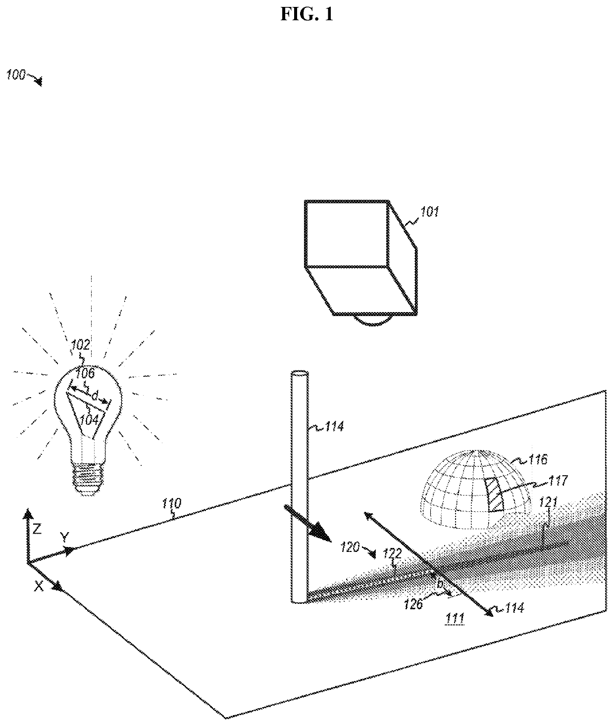
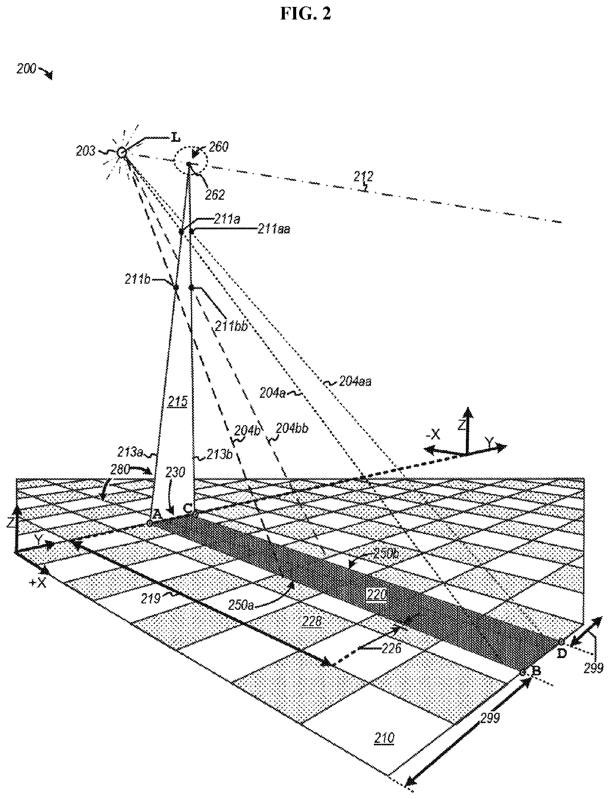
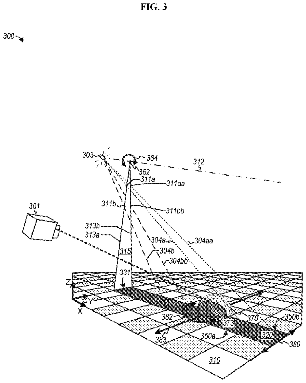
[0101]For the purpose of illustration, the present invention is shown in the preferred embodiments of apparatuses, methods, and systems, for generating one or more edges of luminosity to form three-dimensional models of objects or environments. In broad embodiment, the present invention comprises one or more light sources and one or more shadow casters, which generate one or more edges of luminosity across objects or areas being modeled, one or more means of detecting the one or more edges of luminosity, a means of moving the one or more edges of luminosity relative to the objects or areas being modeled, and a means of generating three-dimensional models of the objects or areas being modeled, as well as related methods and systems. Some embodiments move the one or more shadow casters, some embodiments move the one or more light sources, and some embodiments move the object through the one or more edges of luminosity. Various embodiments or examples may be implemented in numerous way...


PUM

PropertyMeasurementUnit
diameteraaaaaaaaaa
widthaaaaaaaaaa
diameteraaaaaaaaaa

Abstract

Disclosed herein are various embodiments relate generally to computer vision, graphics, image scanning, and image processing as well as associated mechanical, electrical and electronic hardware, computer software and systems, and wired and wireless network communications to form at least three-dimensional models or images of objects and environments.

Description

CROSS-REFERENCE TO RELATED APPLICATIONS[0001]This application claims benefit of U.S. Provisional Patent Application No. 62 / 569,353, which was filed on Oct. 6, 2017, and which is incorporated herein by reference in its entirety.STATEMENT REGARDING FEDERALLY SPONSORED RESEARCH OR DEVELOPMENT[0002]Not ApplicableREFERENCE TO SEQUENCE LISTING, A TABLE, OR A COMPUTER PROGRAM LISTING COMPACT DISK APPENDIX[0003]Not ApplicableBACKGROUND OF THE INVENTION1. Field of the Invention[0004]The present invention is in the technical field of scanning devices. More particularly, the preferred embodiments of the present invention relate generally to scanning devices, which generate three-dimensional models of the object being scanned. More particularly, the preferred embodiments of the present invention relate generally to apparatuses, systems and methods, which use shadow casters to generate three-dimensional models of objects or areas being scanned.2. Description of the Related Art[0005]Advances in c...

Claims


Application Information

Patent Timeline
Patent Type & Authority Applications(United States)
IPC IPC(8): G01B11/24A61B34/10A61B34/20A61B90/20A61B90/00A61B90/30G06T15/60
CPCG06T2215/12A61B2090/306A61B34/10A61B2034/105A61B2034/2055A61B2090/365A61B2090/374A61B90/30A61B2090/3762G06T15/60A61B90/20A61B2090/373A61B2090/367G01B11/2433A61B34/20A61B90/37A61B2034/2051G01B11/254G06T17/00G01B11/2527B29C64/10B29C64/264B33Y10/00B33Y30/00A61B1/00167A61B1/00172A61B1/0646A61B1/07A61B90/36A61B2090/372A61B2090/502A61B34/30A61B90/10A61B2034/2048A61B2090/309A61B1/000095A61B1/00194A61B1/0605B64U2101/30F21K9/00F21Y2103/00F21V1/10F21V1/08F21V11/12F21V7/005
Inventor BERNSTEIN, AARON CHARLESLEVINE, JEFFERY A.EDWARDS, PATRICK C.
Owner ADVANCED SCANNERS INC
Why Eureka
Try Eureka