Coated Optical Fibers and Related Apparatuses, Links, and Methods for Providing Optical Attenuation

a technology of coating optical fibers and optical attenuation, applied in the field of optical attenuation, can solve the problems of limiting the performance of optical fiber links, reducing efficiency, speed or reliability, etc., and achieves the effects of avoiding optical detector saturation, limiting the maximum optical power levels, and high output optical power levels

Inactive Publication Date: 2011-04-21
CORNING INC
View PDF76 Cites 19 Cited by
  • Summary
  • Abstract
  • Description
  • Claims
  • Application Information

AI Technical Summary

Benefits of technology

[0008]In this manner as an example, an optical light source may be controlled to produce light directed towards the optical fiber at higher output optical power levels while limiting the maximum optical power levels in the optical fiber. For example, an optical fiber may be limited in optical power to meet eye safety requirements or to avoid optical detector saturation. However, driving the optical light source to a maximum optical power output level beyond such limitations may be desired. For example, the linearity of an optical light source may improve when driven above certain threshold drive current. Further, driving an optical light source at higher optical power levels may produce a far-field light pattern that excites a limited number or predetermined set of modes or mode groups. Limiting the number of excited modes or mode groups in a multi-mode optical fiber link can reduce modal dispersion and improve optical fiber link bandwidth as a result. As another example, overdriving an optical light source can compensate for variation conditions that can reduce optical power such as temperature or aging effects of the optical light source.
[0009]Further, disposing a coating material on a detector end of an optical fiber to optically attenuate light may also be desired. Disposing a coating material on a detector end of an optical fiber to optically attenuate light may allow limiting certain modes or mode groups of light detected by an optical detector from the optical fiber, which may reduce modal dispersion thereby increasing bandwidth performance.
[0010]The material type of the coating material and / or the thickness of the coating material may be selectively controlled to control the amount of optical attenuation provided by the coating material. The thickness of the coating material may be controlled by a coating material removal process or a process to deposit the desired thickness of coating material, as examples. In other embodiments, the coating material disposed on the optical fiber end may be disposed in an optical attenuation pattern. The optical attenuation pattern may block or attenuate certain modes or mode groups of light while allowing other modes or mode groups of light to pass through the coating material. In this manner, the optical attenuation pattern may serve to limit the number of modes or mode groups excited in an optical fiber and / or the number of modes or mode groups detected by an optical detector to limit modal dispersion, thus increasing bandwidth performance.

Problems solved by technology

However, limiting the maximum optical power level to a predefined maximum optical power level, such as to meet eye safety requirements for example, may limit performance of an optical fiber link.
Departures from this optimal power can reduce efficiency, speed or reliability.

Method used


Image

  • Coated Optical Fibers and Related Apparatuses, Links, and Methods for Providing Optical Attenuation
  • Coated Optical Fibers and Related Apparatuses, Links, and Methods for Providing Optical Attenuation
  • Coated Optical Fibers and Related Apparatuses, Links, and Methods for Providing Optical Attenuation

Examples


Embodiment Construction

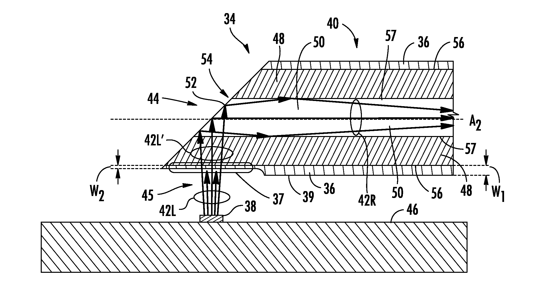
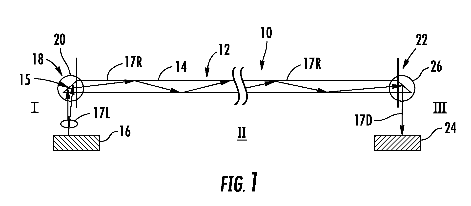
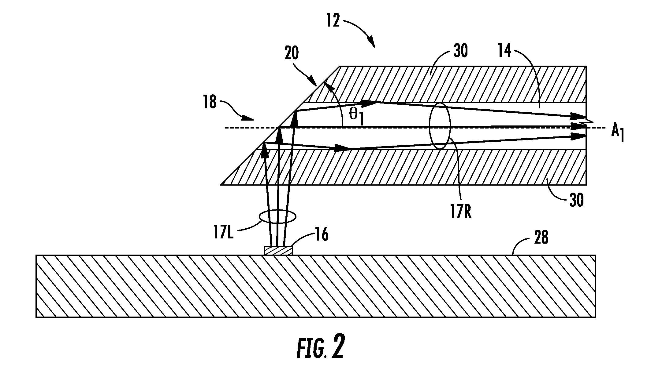
[0007]Embodiments disclosed in the detailed description include coated optical fibers and related apparatuses, links, and methods for optically attenuating light either launched into an optical fiber or received from an optical fiber. In one embodiment, the optical fiber includes an optical fiber end. For example, the optical fiber end may be a source end configured to be placed or mounted adjacent an optical light source to receive light launched from the optical light source and / or a detector end configured to be placed or mounted adjacent an optical detector that receives light from the optical fiber. A coating material is disposed on at least a portion of the optical fiber end and configured to optically attenuate a portion of light directed to the optical fiber end.

[0008]In this manner as an example, an optical light source may be controlled to produce light directed towards the optical fiber at higher output optical power levels while limiting the maximum optical power levels ...


PUM


Abstract

Coated optical fibers and related apparatuses, links, and methods for optically attenuating light directed to or from optical fibers are disclosed. In one embodiment, an optical fiber includes an optical fiber end. The optical fiber end may be a source end and / or a detector end, and may be angle-cleaved. A coating material is disposed on at least a portion of the optical fiber end and configured to optically attenuate a portion of light directed to the optical fiber end. The material type of the coating material and / or the thickness of the coating material may be selectively controlled to control the amount of optical attenuation. The thickness of the coating material may also be controlled to provide the desired thickness of coating material onto at least a portion of the optical fiber end. The coating material may also be selectively patterned to improve the bandwidth of a multi-mode optical link.

Description

BACKGROUND[0001]1. Field of the Disclosure[0002]The technology of the disclosure relates to optical attenuation of light communicated to and / or from an optical fiber.[0003]2. Technical Background[0004]Optical fibers can be used to transmit or process light in a variety of applications. Examples include delivering light to and receiving light from integrated optical components or devices formed on substrates, and transmitting information channels in wavelength-division multiplexed optical communication devices and systems. Other examples include forming fiber optic switch matrix devices or fiber array to array connectors, and producing optical gain for optical amplification or laser oscillation. Optical fibers essentially operate as “light pipes” to confine light within the optical fiber boundary and transfer light from one point to another.[0005]A typical optical fiber may be simplified as having an optical fiber core and a cladding layer surrounding the optical fiber core. The refr...

Claims


Application Information

Patent Timeline
Patent Type & Authority Applications(United States)
IPC IPC(8): G02B6/00
CPCG02B6/02033G02B6/03694G02B6/02395G02B6/4214G02B6/43G02B6/4203
Inventor DEMERITT, JEFFERY A.SUTHERLAND, JAMES S.
Owner CORNING INC
Why Eureka
Try Eureka