Pulsed laser machining method and installation, particularly for welding, with variation of the power of each laser pulse

A laser processing method and laser pulse technology, applied in laser welding equipment, welding equipment, metal processing equipment, etc., can solve the problems of complex and difficult welding quality

Active Publication Date: 2013-05-15
相干瑞士股份公司
View PDF7 Cites 13 Cited by
  • Summary
  • Abstract
  • Description
  • Claims
  • Application Information

AI Technical Summary

Problems solved by technology

Controlling the quality of welds formed becomes complex and difficult

Method used


Image

  • Pulsed laser machining method and installation, particularly for welding, with variation of the power of each laser pulse
  • Pulsed laser machining method and installation, particularly for welding, with variation of the power of each laser pulse
  • Pulsed laser machining method and installation, particularly for welding, with variation of the power of each laser pulse

Examples


Embodiment Construction

[0021] Laser processing method of the present invention comprises the steps:

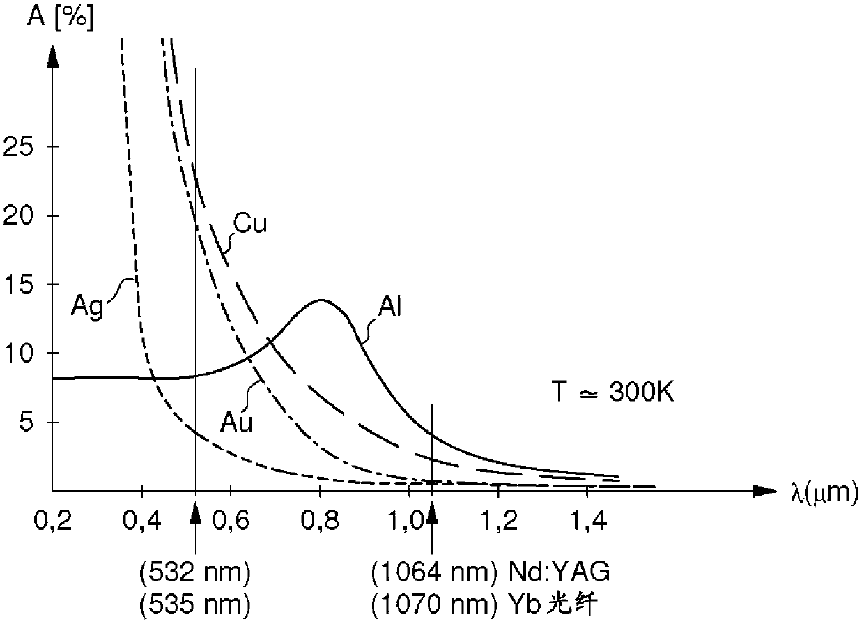
[0022] A) A laser source is used to generate a laser beam formed by a series of laser pulses with a wavelength of 700-1200 nm.

[0023] B) Using a nonlinear crystal to double the frequency of a portion of the laser beam.

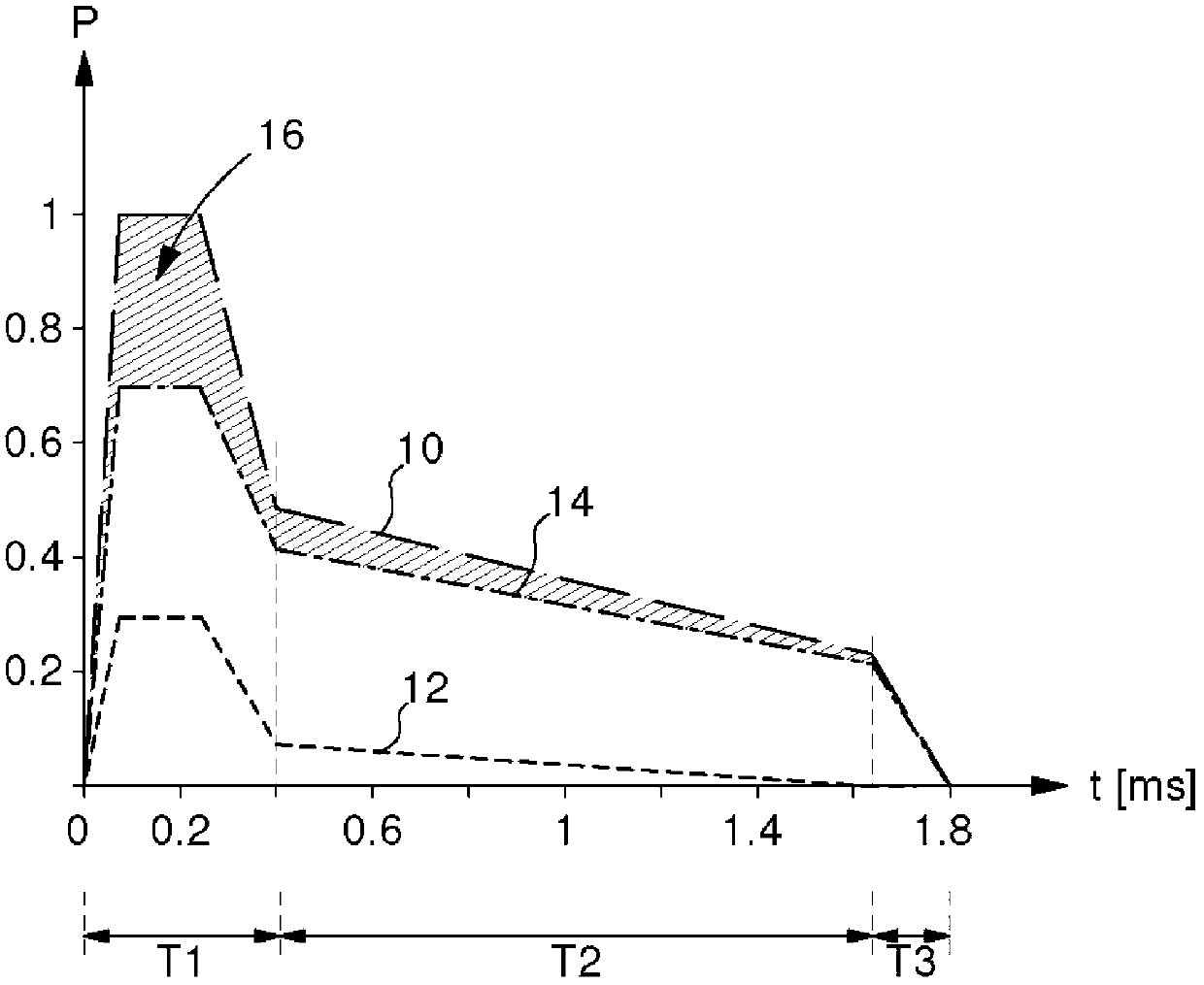
[0024] C) Vary the power during each emitted laser pulse such that, over the entire period of this laser pulse, the power profile has maximum peak power in the initial sub-period T1 or a portion of the pulse has maximum power for a duration longer than the initial sub-period T1 The period is longer and occurs in a subsequent second intermediate sub-period T2, with a power lower than said maximum power throughout the entire intermediate sub-period.

[0025] The variation in maximum power is at least twice the average power over the entire period of the laser pulse, increasing to said maximum power in less than 3 / 10 millisecond (0.3 ms) from the start of each laser pulse.

[0026]...


PUM

PropertyMeasurementUnit
wavelengthaaaaaaaaaa
strengthaaaaaaaaaa
strengthaaaaaaaaaa

Abstract

The laser machining method involves the following steps: A) using a laser source to generate a laser beam at an initial wavelength of between 700 and 1200 nanometers and formed of a succession of laser pulses (10); B) doubling the frequency of part (12) of the laser beam using a non-linear crystal; C) varying the power during each emitted laser pulse (10) so that the power profile over the period of this laser pulse has, in an initial sub-period (T1), a maximum power peak or a pulse part with a maximum power and, in an intermediate sub-period (T2), of duration longer than the initial sub-period, a power lower than said maximum power over all of this intermediate sub-period. The power of the laser is varied in such a way that the maximum power has a value at least twice as high as the mean power over the period of the laser pulse and that the rise time taken to increase to a maximum power from the start of each laser pulse is shorter than 0.3 milliseconds. The machining method relates in particular to the welding of highly reflective metals such as copper, gold, silver or an alloy containing one of these metals. The intention also relates to a laser machining installation for implementing the method described hereinabove.

Description

technical field [0001] The invention relates to the field of laser welding, in particular laser welding of highly reflective materials such as copper, gold, silver, aluminum and alloys comprising one of these metals. More specifically, the present invention relates to a laser welding method and a device for carrying out said method, wherein a coherent light source generates a laser beam with a wavelength of 700-1200 nanometers, such as a Nd:YAG laser or a fiber laser. A nonlinear crystal is provided to double the frequency portion of the laser beam, thereby increasing processing efficiency. Background technique [0002] US Patent No. 5083007 discloses a laser welding device, including: Nd: YAG laser source, which is optically pumped by a flash lamp to generate coherent light with a wavelength of 1064 nanometers (nm); and a non- Linear crystals (such as LiNbO 3 or KTP), the crystal partially doubles the frequency of light produced by the laser source. At the output of the ...

Claims


Application Information

Patent Timeline
Patent Type & Authority Applications(China)
IPC IPC(8): B23K26/20B23K26/06H01S3/109
CPCB23K26/063B23K26/20B23K2203/12H01S3/109B23K2203/08B23K2203/10B23K26/0622B23K26/22B23K2103/08B23K2103/10B23K2103/12B23K26/21
Inventor U·迪尔C·鲁提曼B·弗赖
Owner 相干瑞士股份公司
Why Eureka
Try Eureka