Device for moulding a bladed part of a turbomachine

a technology of turbomachines and blades, which is applied in the direction of machines/engines, mechanical equipment, other domestic objects, etc., can solve the problems of inability to specifically adapt and optimise moulds for one function, inability to carry out other functions, and relatively fragile composite materials of bladed parts

Pending Publication Date: 2022-11-03
SN DETUDE & DE CONSTR DE MOTEURS DAVIATION S N E C M A
View PDF4 Cites 0 Cited by
  • Summary
  • Abstract
  • Description
  • Claims
  • Application Information

AI Technical Summary

Problems solved by technology

However, the disadvantage of this technology is that the mould cannot be specifically adapted and optimised for one of these steps since it must also be suitable for carrying out the other step.
Furthermore, this mould is not suitable for carrying out other functions such as the co-injection of a metal shield on a leading edge of the bladed part.
The composite material of the bladed part is relatively fragile, and in particular sensitive to impact, and it is known to protected it by means of

Method used


Image

  • Device for moulding a bladed part of a  turbomachine
  • Device for moulding a bladed part of a  turbomachine
  • Device for moulding a bladed part of a  turbomachine

Examples


Embodiment Construction

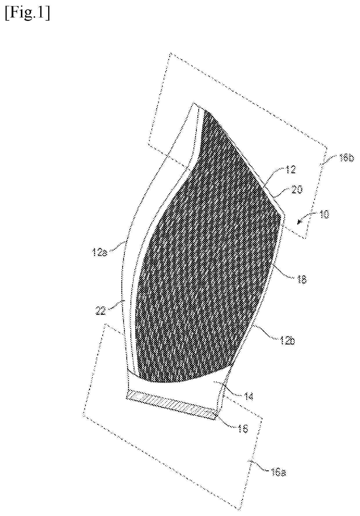
[0070]Reference is first made to FIG. 1 which illustrates a composite material bladed part 10 for a turbomachine, this bladed part 10 being for example a fan vane or a rectifier blading for example of a secondary flow in the case of a turbofan engine.

[0071]The bladed part 10 comprises a blade 12. In the illustrated case where the part 10 is a fan blade, this blade 12 is connected by a stilt 14 to a root 16 which has, for example, a dovetail shape and is shaped so as to be engaged in a recess with a shape complementary to a rotor disc, in order to retain the vane on this disc.

[0072]In the alternative case where the part 10 is a rectifier blade, the blade 12 extends between two platforms 16a, 16b which extend substantially parallel to each other and perpendicular to an axis of elongation of the blade 12.

[0073]The blade 12 comprises a leading edge 12a and a trailing edge 12b of the gases flowing into the turbomachine. The blade 12 has a curved or twisted aerodynamic profile and compris...


PUM


Abstract

A device for moulding at least one bladed part of a turbomachine, including a base, a mould formed from several parts that are interlocked with each other, this mould being applied to the base and first sealing means being mounted between the mould and the base, a bell-shaped dome mounted on the mould and around the mould, this bell-shaped dome being applied to the base and second sealing means being mounted between the bell-shaped dome and the base, this bell-shaped dome being configured to be held clamped against the base and including inner surfaces cooperating by corner effect with complementary outer surfaces of the mould in order to apply a clamping force on the parts of this mould.

Description

TECHNICAL FIELD OF THE INVENTION[0001]The present invention relates to a device for moulding a bladed part of a turbomachine, as well as to a method using this device.BACKGROUND[0002]The prior art comprises in particular the documents FR-A1-2 956 057, FR-A1-3 014 008, FR-A1-3 029 134, FR-A1-3 032 147, FR-A1-3 046 564, FR-A1-3 051 386 and WO-A1-2014 / 076 408.[0003]The use of composite materials is advantageous in the aeronautical industry in particular because these materials have interesting mechanical performances for relatively low masses.[0004]One process for manufacturing a composite part for the aeronautical industry, which is well known to the person skilled in the art, is the RTM process, the initials of which refer to the acronym of Resin Transfer Molding.[0005]This is a process for producing a part from a composite material based on resin-impregnated fibres. Such a process is used, for example, to manufacture a turbomachine bladed part such as a fan blade or a rectifier blad...

Claims


Application Information

Patent Timeline
IPC IPC(8): B29C70/48B29C33/00B29C70/54F01D5/28
CPCB29C70/48B29C33/0038B29C70/541F01D5/282B29L2031/08B29D99/0025B29C70/86B29C33/44B29C33/20F05D2300/603F05D2300/224B29C61/0658
Inventor BLAISE, MAXIME MARIE DESIREFABRE, HUBERT JEAN MARIEPOTE, JEFF
Owner SN DETUDE & DE CONSTR DE MOTEURS DAVIATION S N E C M A
Why Eureka
Try Eureka