
Multi-pole low-voltage power circuit breaker

A circuit breaker, multi-pole technology, applied in circuits, high-voltage/high-current switches, electrical components, etc., can solve the problems of large damage risk of circuit breakers, incomplete circuit breakers, etc., and achieve the effect of optimized discharge and treatment

Active Publication Date: 2019-05-31
SCHNEIDER ELECTRIC IND SAS
View PDF13 Cites 0 Cited by
  • Summary
  • Abstract
  • Description
  • Claims
  • Application Information

AI Technical Summary

Problems solved by technology

[0007] However, these circuit breakers are not entirely satisfactory for some modern uses, especially when these circuit breakers are intended to operate at high voltages, such as for low voltages greater than or equal to 500V AC per phase and possibly up to 690V AC
[0008] In particular, these circuit breakers present a greater risk of damage following excessive overpressure of extinguishing gas inside the housing of the circuit breaker

Method used


Image

  • Multi-pole low-voltage power circuit breaker
  • Multi-pole low-voltage power circuit breaker
  • Multi-pole low-voltage power circuit breaker

Examples


Embodiment Construction

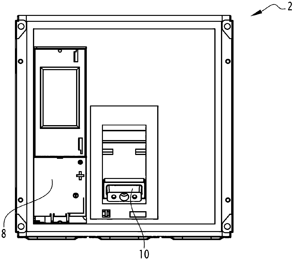
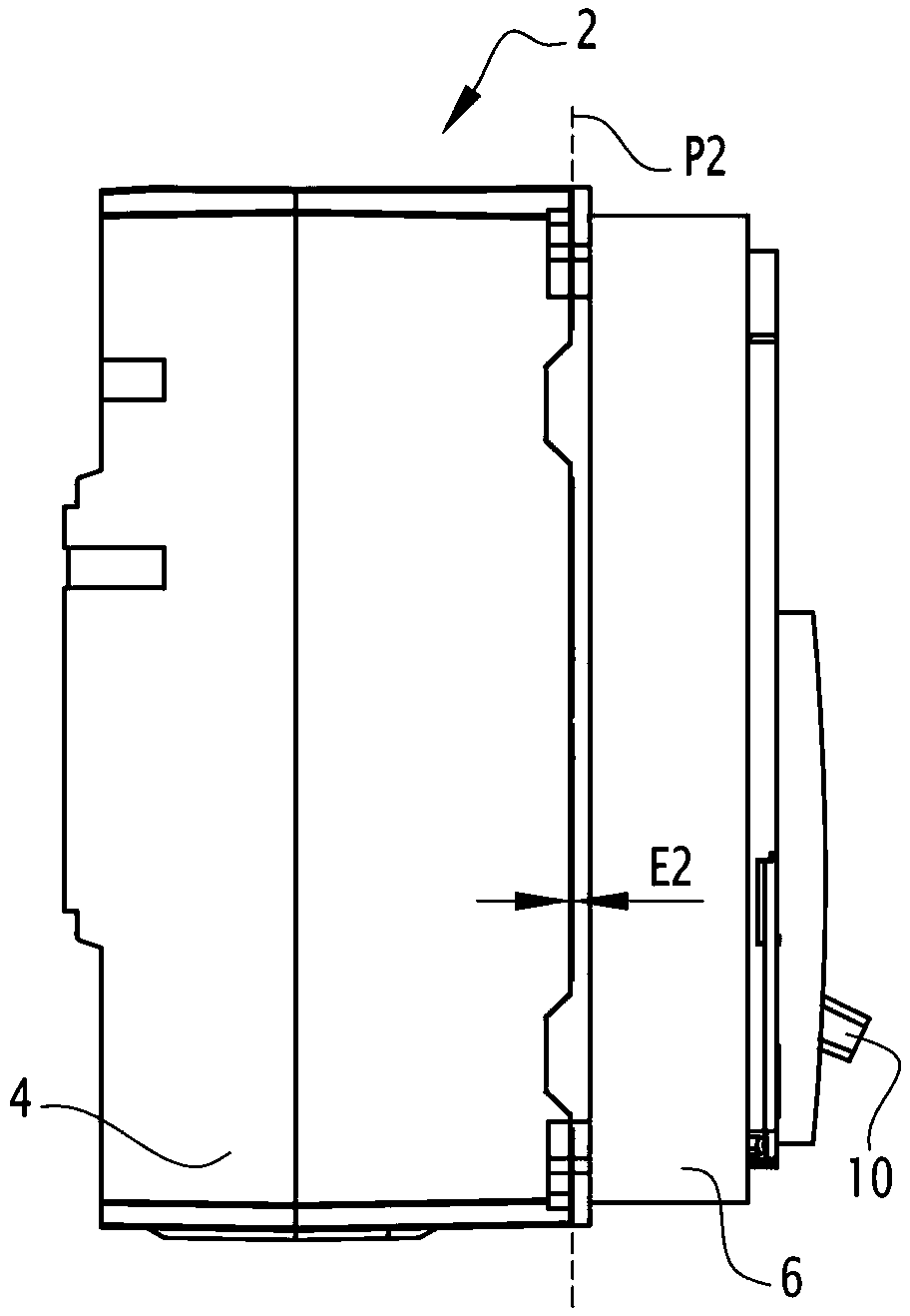
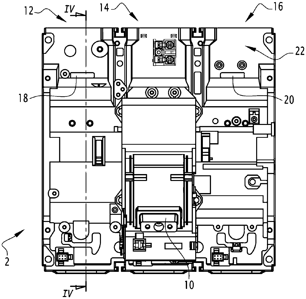
[0034] Figure 1 to Figure 4 A low voltage multi-pole circuit breaker 2 is shown comprising a molded housing comprising a main body 4 and a removable cover 6 added to the main body 4 .

[0035] When the cover 6 is mounted on the body 4 it covers the main face 22 of the body 4 . The main face 22 is, for example, the front of the body 4 .

[0036] more specifically from figure 2 As can be seen in , the cover 6 is fastened to the body 4 while leaving a peripheral opening between the cover 6 and the body 4 . This peripheral opening extends over the periphery of the cover 6 .

[0037] The cover 6 together with the face 22 delimits the inner volume. A peripheral opening communicates this internal volume with the outside of the housing of the circuit breaker 2 .


PUM


Abstract

A low-voltage multipolar circuit breaker 2 includes a moulded housing including a main body that is divided into interior compartments, each associated with one pole 12,14,16 of the circuit breaker, and a cover that is mounted on the main body covering a main face 22 of the body. The circuit breaker includes, for each pole, electrical contacts that can be separated by a device of a switching mechanism and an arc-extinguishing chamber. For at least two of the poles, the main face includes an additional aperture 18,20, each placed directly above the spark guard of the corresponding pole and placing the arc-extinguishing chamber of this pole in communication with the interior volume delimited by the cover and the main face, and the cover is attached to the main body while leaving a peripheralopening between the cover and the main body, placing the interior volume in communication with the exterior of the housing.

Description

technical field [0001] The invention relates to a low-voltage multi-pole circuit breaker. Background technique [0002] Low-voltage multi-pole circuit breakers are known which comprise a molded case divided into internal compartments, each associated with one pole of the circuit breaker and each enclosing separable electrical contacts, the displacement of which is determined by a common mechanism for all poles. controlled by the actuator and driven by the trip mechanism. [0003] An example of such a circuit breaker is described in FR-2780549-A1. [0004] These circuit breakers are more specifically used to interrupt high-intensity currents and are usually located between 630A and 6300A. Breaking of current is accomplished in air by separating the electrical contacts using electrical interrupters associated with each pole. [0005] A known problem with these circuit breakers stems from the fact that hot ionized gases called extinguishing gases are produced when the electr...

Claims


Application Information

Patent Timeline
IPC IPC(8): H01H9/04H01H9/30H01H9/34
CPCH01H9/342H01H9/346H01H2009/348H01H33/53H01H33/74H01H2213/004H01H33/022H01H33/08
Inventor M.里瓦尔C.多梅内奇D.罗塔C.托代斯基尼
Owner SCHNEIDER ELECTRIC IND SAS
Learn More