Rolling bearing with rolling bodies and flange

a technology of rolling bearings and flanges, applied in the direction of shaft assemblies, mechanical equipment, rotary machine parts, etc., can solve the problems of coming into contact and the damage of the umbrella effect, and achieve the effect of limiting pollution ingress and sufficient rigidity

Active Publication Date: 2015-06-30
AB SKF
View PDF10 Cites 0 Cited by
  • Summary
  • Abstract
  • Description
  • Claims
  • Application Information

AI Technical Summary

Benefits of technology

[0006]By virtue of the invention, the geometry of the flange enables it to exhibit a sufficient rigidity to ensure a function of isolation of the rolling chamber from the outside, because of the existence of the two setbacks, while exhibiting a relatively small axial bulk, which limits the risk of interference between this flange and its environment, both on the side of the rolling chamber and towards the outside. Finally, the folded-back edge makes it possible to limit the ingress of pollution into the rolling chamber without the risk of extending outside the rings as a result of an umbrella effect.

Problems solved by technology

With the equipment known from JP-A-2000 249 154, this umbrella effect is all the more damaging when the edge of the flange opposite to its means for fastening onto a ring is oriented towards the outside of the rolling bearing, to the extent that it extends laterally beyond the rolling bearing when the flange is not at right angles to the axis of rotation of the rolling bearing.
On the other hand, if the geometry of the flange is modified, the latter risks coming into contact with the cage which holds the balls in place in the rolling chamber.

Method used


Image

  • Rolling bearing with rolling bodies and flange
  • Rolling bearing with rolling bodies and flange
  • Rolling bearing with rolling bodies and flange

Examples


Embodiment Construction

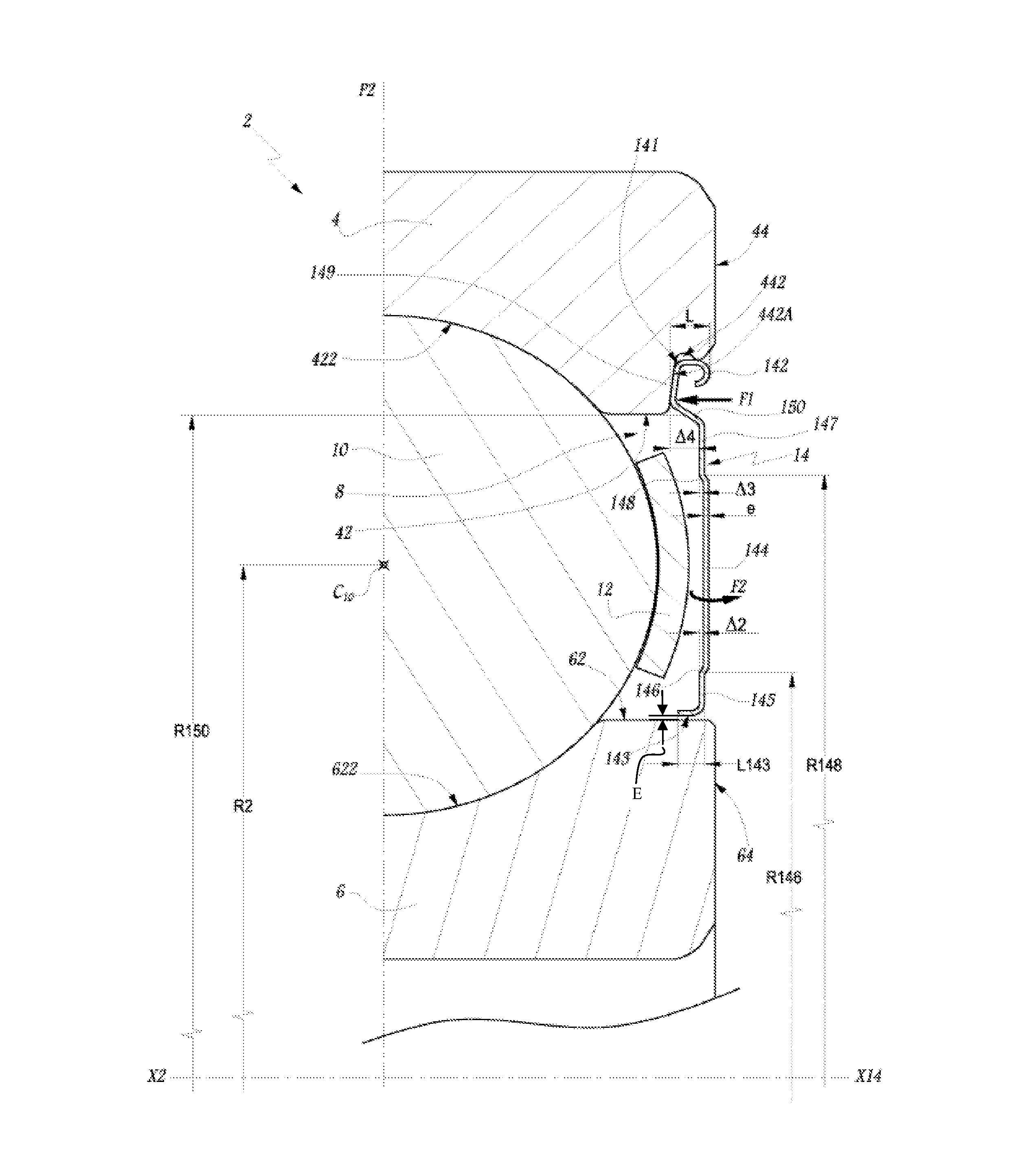
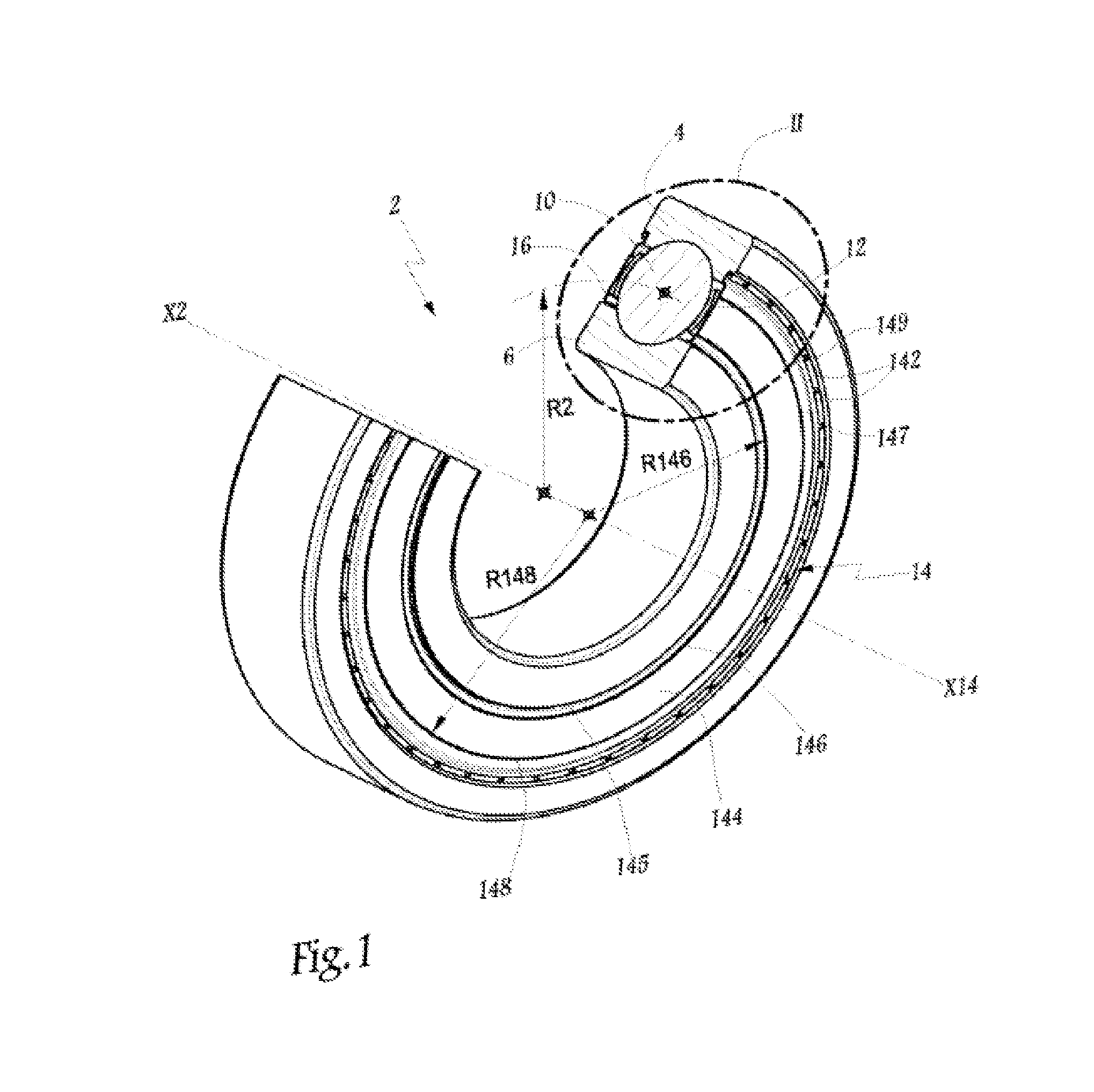
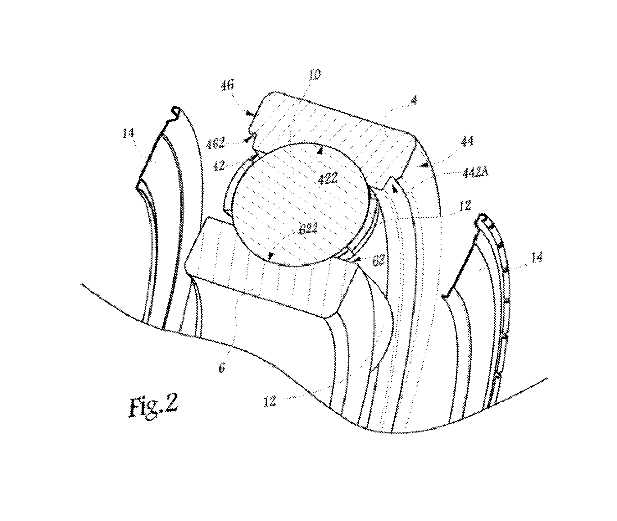
[0024]The rolling bearing 2 represented in the figures comprises a non-rotating outer ring 4 and a rotating inner ring 6 between which there is defined a rolling chamber 8 in which is arranged a series of balls 10 held in place by a cage 12.

[0025]As a variant, other rolling bodies can be used, for example rollers or needles.

[0026]X2 is used to denote the central axis of the rolling bearing 2, that is to say the relative axis of rotation of the rings 4 and 6.

[0027]Two flanges 14 and 16 are respectively mounted on the outer ring 4 and extend in the direction of the inner ring 6, in order to isolate the rolling chamber 8 from the outside.

[0028]R2 denotes the radius of a circle passing through the centres C10 of the balls 10 that is qualified as mean radius of the roller bearing 2. This mean radius is sometimes qualified as “pitch”. This mean radius R2 has a value equal to approximately 100 mm. In other words, the rolling bearing 2 has relatively large dimensions, such that the manufact...


PUM


Abstract

A rolling bearing with rolling bodies includes an outer ring, an inner ring and rolling bodies arranged in a rolling chamber. The rolling bearing includes at least one flange mounted on a first ring and extending to a second ring and fastened onto the first ring and a first annular band at right angles to an axis of rotation of the rings and offset, along the axis, relative to the fastened portion. The flange provides a second annular band and a third annular band arranged respectively radially inside and radially outside the first band and offset axially in the direction of the rolling bodies, using a first setback and a second setback. An edge of the flange, opposite to the portion fastened onto the first ring, is folded back towards the rolling chamber and extends in a direction parallel to a radial surface of the second ring.

Description

CROSS-REFERENCE TO RELATED APPLICATIONS[0001]This application claims priority to French patent application no. 1256059 filed Jun. 26, 2012, the contents of which are fully herein incorporated by reference.TECHNICAL FIELD[0002]The present invention relates to a rolling bearing with rolling bodies to be used to support, relative to one another, two parts that need to have a relative rotational movement.BACKGROUND OF THE INVENTION[0003]In the field of rolling bearings, it is known practice to equip a rolling bearing with one or two flanges provided to isolate, from the outside, a rolling chamber defined between the two rings of a rolling bearing and in which rolling bodies are arranged. JP-A-2000 249 154 thus proposes mounting two flanges on the two opposite sides of a ball bearing. These flanges have a relatively great thickness and their geometry is such that the inner and outer rings of the rolling bearing have to be substantially wider, in a direction parallel to the axis of rotati...

Claims


Application Information

Patent Timeline
Patent Type & Authority Patents(United States)
IPC IPC(8): F16C33/80F16J15/44F16C33/78F16C33/30F16C19/06
CPCF16C33/30F16C33/7889F16C33/785F16J15/44F16C2226/52F16C19/06F16C2240/40F16C2240/70F16C2240/30F16C2300/02
Inventor CHARLES, EMMANUELCONSTANT, BRUNO
Owner AB SKF
Why Eureka
Try Eureka