Image recording system

a technology of image recording system and image, which is applied in the field of image recording system, can solve the problems of not being picked up and reproduced too high intensity, and distorted representation of pulsed light sources by the image recording system, so as to improve the recognition of pulsed light sources, improve the sense of smell, and increase the effect of traffic safety

Inactive Publication Date: 2010-01-21
ROBERT BOSCH GMBH
View PDF9 Cites 16 Cited by
  • Summary
  • Abstract
  • Description
  • Claims
  • Application Information

AI Technical Summary

Benefits of technology

[0005]The present invention may permit substantially improved sensing of pulsed light sources, to thus improve the recognition of pulsed light sources and thereby to increase traffic safety. To this end, the image recording system may advantageously include a radiation sensor having generally identical intensity dynamics, having a generally identical opening angle and a generally identical direction of view as the camera, for sensing pulsed light sources. The image recording system also includes a control device which ascertains the discrepancy based on the signals from the camera and the radiation sensor. In one example embodiment, as a function of the discrepancy determined, a warning signal is generated which indicates deficiencies in the display representation to the driver. Additionally, the display may be controlled to the dark state temporarily, or perhaps switched off. In more complex embodiment variants, the exposure phase of the camera is synchronized with the ON phase of the light source as a function of the discrepancy. In another example embodiment variant, the image recording system is operated in a linear mode on one hand, and in a non-linear mode on the other hand. Recorded images are compared. In response to the appearance of pulsed light sources, at least partial areas of the images acquired in the non-linear mode are replaced by corresponding partial areas of the images acquired in the linear mode.

Problems solved by technology

Since these cameras do not expose continuously, thus during the complete frame phase, but only in certain time intervals (e.g., shutter time in the case of CCD cameras), there is the risk that pulsed light sources picked up by the image recording system will be distortedly represented.
In this connection, distortedly represented means that the light sources are picked up and reproduced with too low an intensity, with too high an intensity or, in the worst case, are not picked up and reproduced by the image recording system at all.
However, the faulty sensing and representation of the pulsed light sources can give rise to dangerous situations.
One risk comes about, for example, because the driver of the host vehicle, upon glancing at his / her night vision display, no longer recognizes that the preceding vehicle is braking.
At this point, there is a threat of a rear-end collision.
When driving at night, preceding or oncoming vehicles cannot be recognized as well on the display, since the pulsed light sources are no longer clearly represented.

Method used


Image

  • Image recording system
  • Image recording system
  • Image recording system

Examples


Embodiment Construction

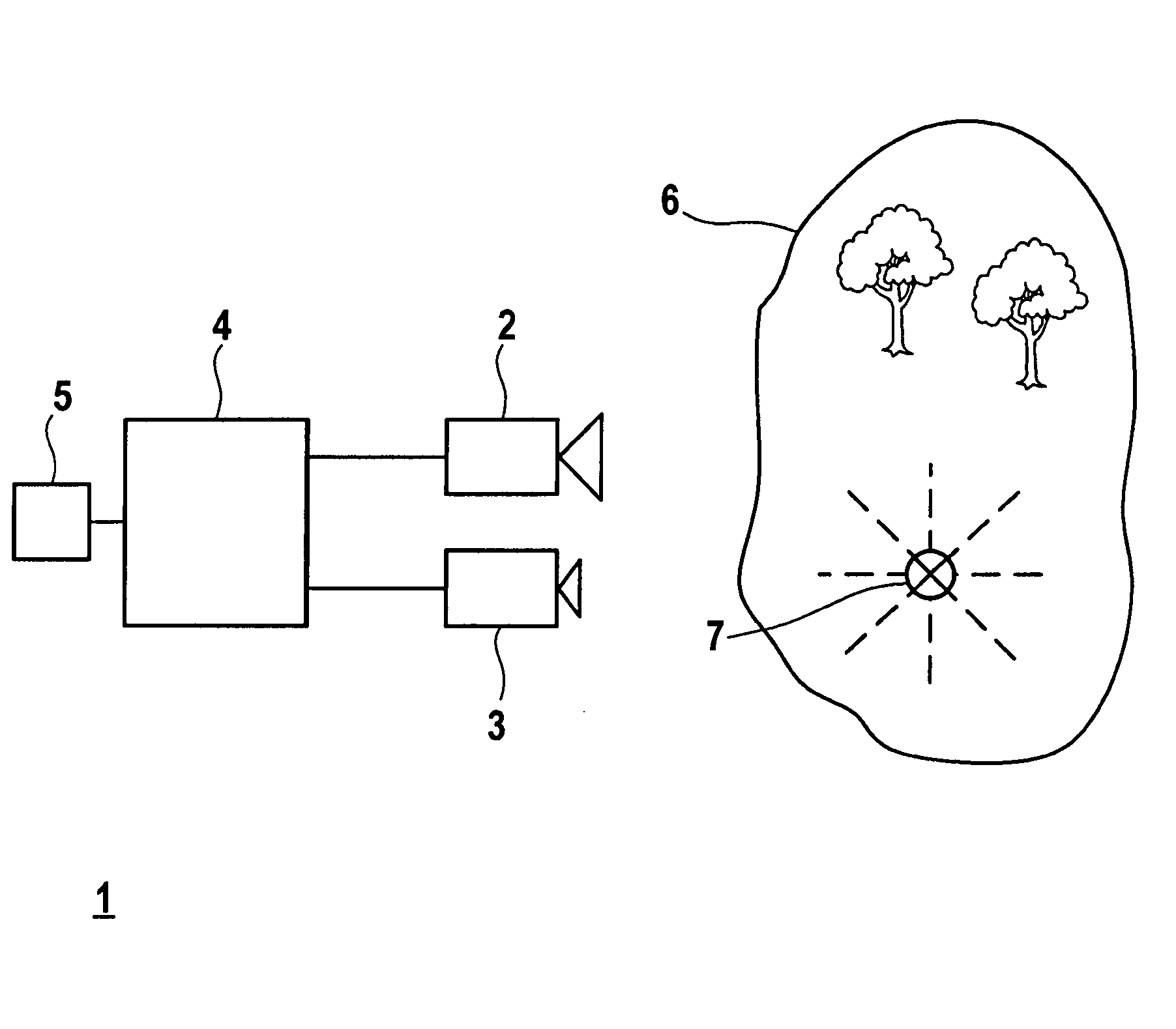
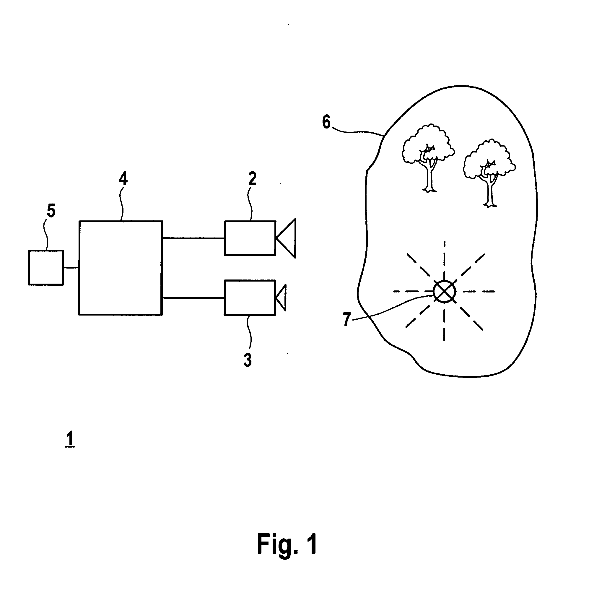
[0015]In the following, exemplary embodiments of the present invention are described. A first exemplary embodiment is explained with reference to FIG. 1, which shows a block diagram of an image recording system 1 and an image scene 6. Image recording system 1 includes a camera 2, in particular a CCD or CMOS camera. In addition, image recording system 1 includes a radiation detector 3 which has intensity dynamics corresponding to the greatest extent possible with camera 2, as well as the same opening angle and the same direction of view as camera 2. Radiation detector 3 is preferably a photodiode or a phototransistor. Camera 2 and radiation detector 3 are connected to a control device 4. Control device 4 is connected to a display 5.

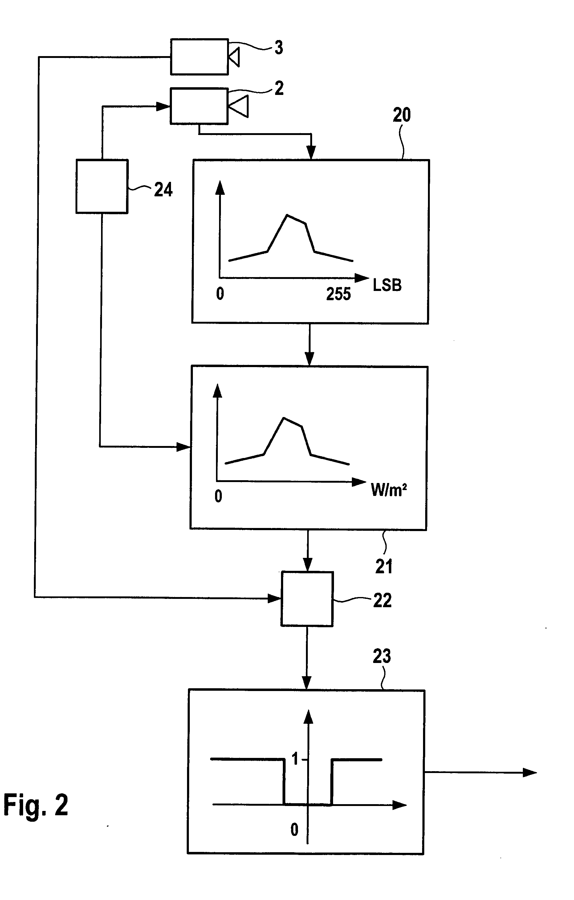
[0016]Radiation detector 3 quasi continuously ascertains an average brightness level of entire image scene 6 which is picked up by image recording system 1. From the histogram of the camera image, which is formed for an exposure control, an average brightn...


PUM


Abstract

An image recording system having a CCD camera or CMOS camera for picking up the surroundings of a vehicle. The image recording system additionally includes a radiation sensor for sensing a pulsed light source, as well as a control device, controlled by the radiation sensor, which determines the discrepancy between the exposure phase of the camera and the ON phase of the pulsed light source and minimizes it by synchronizing the exposure phase with the ON duration

Description

FIELD OF THE INVENTION[0001]The present invention relates to an image recording system.BACKGROUND INFORMATION[0002]An image recording system may be used, for example, in motor vehicles to obtain images of the vehicle surroundings and, in conjunction with assistance systems, to facilitate the driver in guiding the vehicle. In particular, such an image recording system also picks up vehicles which are moving in the same traffic lane or adjacent traffic lanes in front of the host vehicle. An image recording system of this type includes at least one image sensor and an optical system that is assigned to this image sensor and images a photo field of the vehicle surroundings onto the image sensor. A task of such assistance systems is the precise measurement of distance, since optical traffic-lane monitoring systems and vehicle-to-vehicle distance monitoring systems function only with sufficient reliability if precise distance values are known. Furthermore, such image recording systems are...

Claims


Application Information

Patent Timeline
Patent Type & Authority Applications(United States)
IPC IPC(8): H04N7/18
CPCB60R1/00B60R2300/106B60R2300/301H04N5/33H04N5/2353H04N5/2354H04N5/2351G06V20/584H04N23/71H04N23/73H04N23/74
Inventor HAUG, KARSTEN
Owner ROBERT BOSCH GMBH
Why Eureka
Try Eureka