Illumination device and reflection type liquid crystal display device using the same

Inactive Publication Date: 2006-03-28
SAMSUNG DISPLAY CO LTD
View PDF9 Cites 19 Cited by
  • Summary
  • Abstract
  • Description
  • Claims
  • Application Information

AI Technical Summary

Benefits of technology

[0032]Therefore, even when the number of the light sources disposed at a side of the second light guiding plate is increased, the light efficiency of the plurality of light sources

Problems solved by technology

The transmission type liquid crystal display is widely used, but the use of the backlight in

Method used


Image

  • Illumination device and reflection type liquid crystal display device using the same
  • Illumination device and reflection type liquid crystal display device using the same
  • Illumination device and reflection type liquid crystal display device using the same

Examples


Embodiment Construction

[0044]Hereinafter, exemplary embodiments of the present invention will be described in detail with reference to the accompanying drawings.

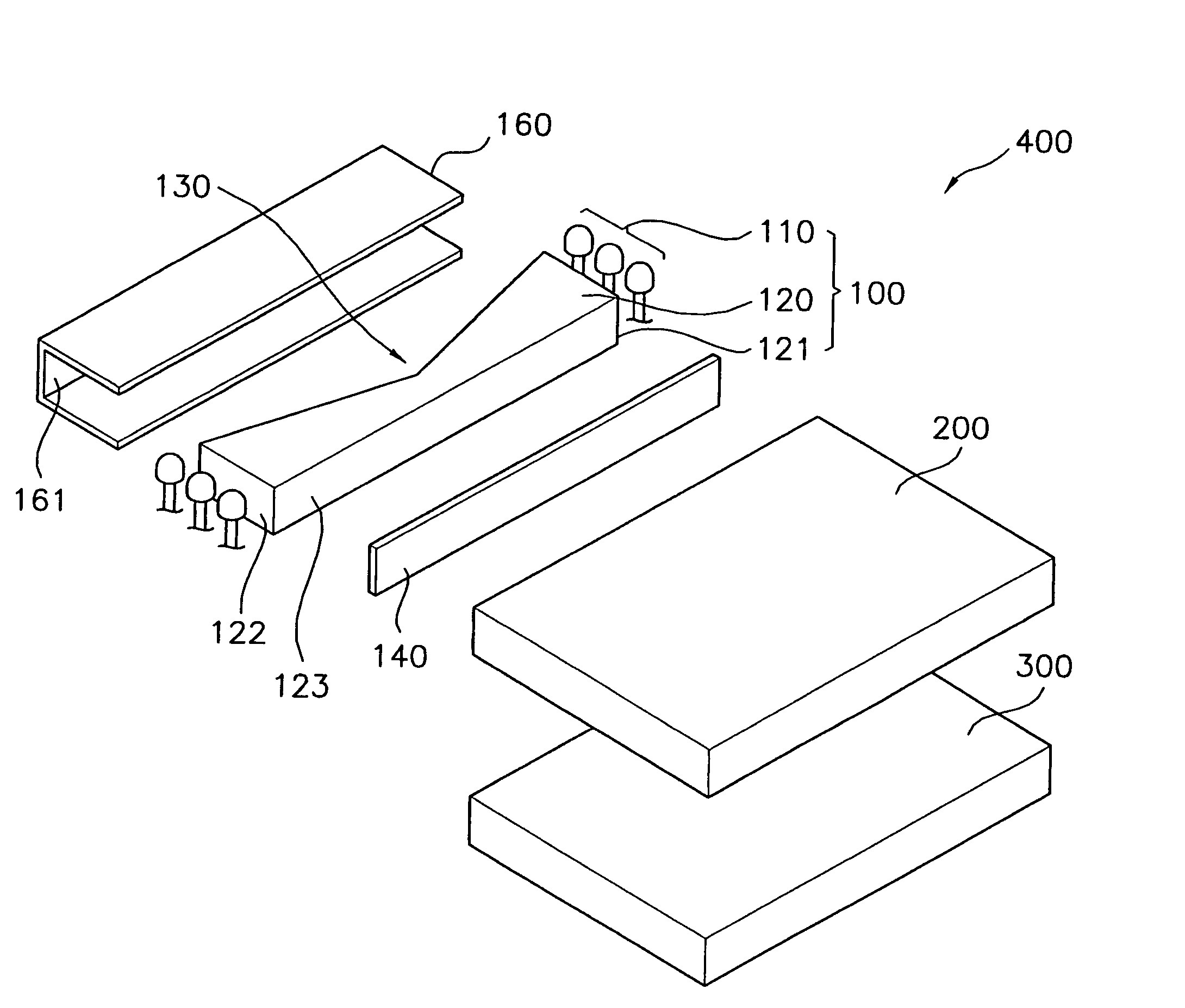
[0045]FIG. 3 is an exploded perspective view schematically showing a reflection type liquid crystal display device according to one exemplary embodiment of the present invention.

[0046]Referring to FIG. 3, the reflection type liquid crystal display device 400 includes a light source section 100, a light guiding section 200 provided at a side of the light source section 100, and a liquid crystal display panel section 300 disposed below the light guiding section 200.

[0047]The light source section 100 includes a plurality of light sources 110 for emitting the light and a second light guiding plate 120 for guiding the light towards the light guiding section 200. The plurality of light sources 110 is arranged at opposite side ends of the second light guiding plate 120. The light sources 110 include a light emitting device in the form of a point-shaped l...


PUM


Abstract

Disclosed are an illumination device capable of improving an optical efficiency of a light generated from a light source and a reflection type liquid crystal device using the, illumination device. Between at least one light source and a first light guiding plate, which is provided to uniformly project the light incident from a first side towards a second side, a second light guiding plate for projecting the incident light towards the first side of the first light guiding plate is provided. A distance between a light projecting portion of the second light guiding plate and a light reflecting portion opposite the light projecting portion becomes narrow as an amount of light flux of the light emitted from at least one light source decreases. Accordingly, the light efficiency can be improved by increasing the probability of variation in optical routes for the light generated from each light source, though the number of the light sources disposed at a side of the second light guiding plate is increased.

Description

CROSS REFERENCE TO RELATED APPLICATIONS[0001]This application is a continuation application of U.S. Ser. No. 10 / 074,466, filed Feb. 12, 2002, now U.S. Pat. No. 6,752,504, issued on Jun. 22, 2004, which claims priority to Korean Patent Application No. 2001-54446, filed on Sep. 5, 2001 and is herein incorporated by reference in its entirety.BACKGROUND OF THE INVENTION[0002]1. Field of the Invention[0003]The present invention relates to an illumination device and a reflection type liquid crystal device using the same, and more particularly to an illumination device capable of improving an optical efficiency of a light emitted from a light source and a reflection type liquid crystal device using the same.[0004]2. Description of the Related Art[0005]Generally, a voltage is applied to a liquid crystal display device to cause a change in an alignment of liquid crystal. As a result, the liquid crystal cells undergoes a change of optical characteristics such as a birefringence, a rotatory po...

Claims


Application Information

Patent Timeline
IPC IPC(8): F21V7/04F21V8/00F21Y101/02G02F1/13357
CPCG02B6/0028G02B6/0038G02F1/133603G02B6/0046G02B6/0068G02B6/0041G02F1/1335
Inventor LEE, KEUN-WOOKIM, JIN-BAEK
Owner SAMSUNG DISPLAY CO LTD
Why Eureka
Try Eureka