

Lighting and/or signalling device with optical guide for a motor vehicle
- Summary
- Abstract
- Description
- Claims
- Application Information
AI Technical Summary
Benefits of technology
Problems solved by technology
Method used
Image

Examples
first embodiment
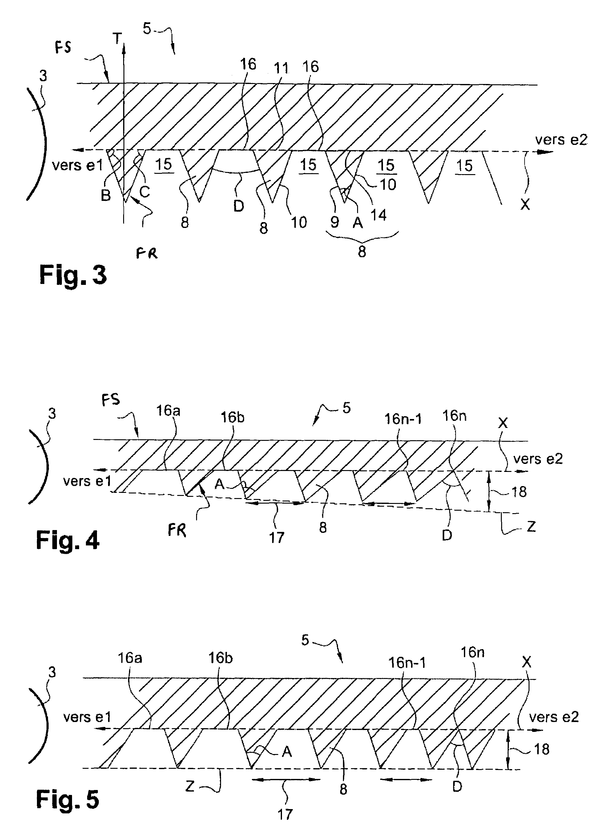
[0055]FIG. 4 shows an optical guide with variable truncation, that is to say one in which the size of the flat surfaces is variable. In the example of FIG. 4, the flat surfaces 16 have decreasing sizes between the end e1 and the end e2 of the optical guide 5, as explained previously. As can be seen in the sectional view of the optical guide 5 of FIG. 4, the flat surfaces 16a, 16b, . . . 16n have sizes different from one another and, more precisely, decreasing sizes. This decrease is obtained by modulating the height of the prisms. More precisely, in the example of FIG. 4: the pitch 17 between two prisms is constant. “Pitch”17 means the length connecting the vertex of a prism with the vertex of the consecutive prism. The pitch 17 is depicted by a double arrow in FIG. 4. In other words, the pitch 17 corresponds to the base of the air prism 15. The pitch 17 between two prisms is preferably of the order of 0.2 to 2 millimeters; the height 18 of the prisms 8 is variable. “Height”18 refer...
second embodiment
[0057]FIG. 5 shows an optical guide 5 with variable truncation. As in the case of FIG. 4, the flat surfaces 16 have decreasing sizes between the end e1 and the end e2 of the optical guide 5. As can be seen in the sectional view of the optical guide 5 of FIG. 5, the flat surfaces 16a, 16b, . . . 16n have decreasing sizes. In this embodiment, the decrease is obtained by modulating the pitch of the prisms. More precisely, in the example of FIG. 5: the pitch 17 between two prisms is variable. The pitch 17 is depicted by a double arrow in FIG. 5. The pitch 17 between two prisms is preferably less than or equal to 2.5 mm, in particular of the order of 0.2 to 2 millimeters; the height 18 of the prisms 8 is constant. The height 18 is depicted by a double arrow in FIG. 5. The height 18 is less than or equal to 2.5 mm, in particular of the order of 0.2 to 2 millimeters. In this embodiment, the pitch 17 of a prism 8 decreases proportionally to the reduction in size of the corresponding flat su...
third embodiment
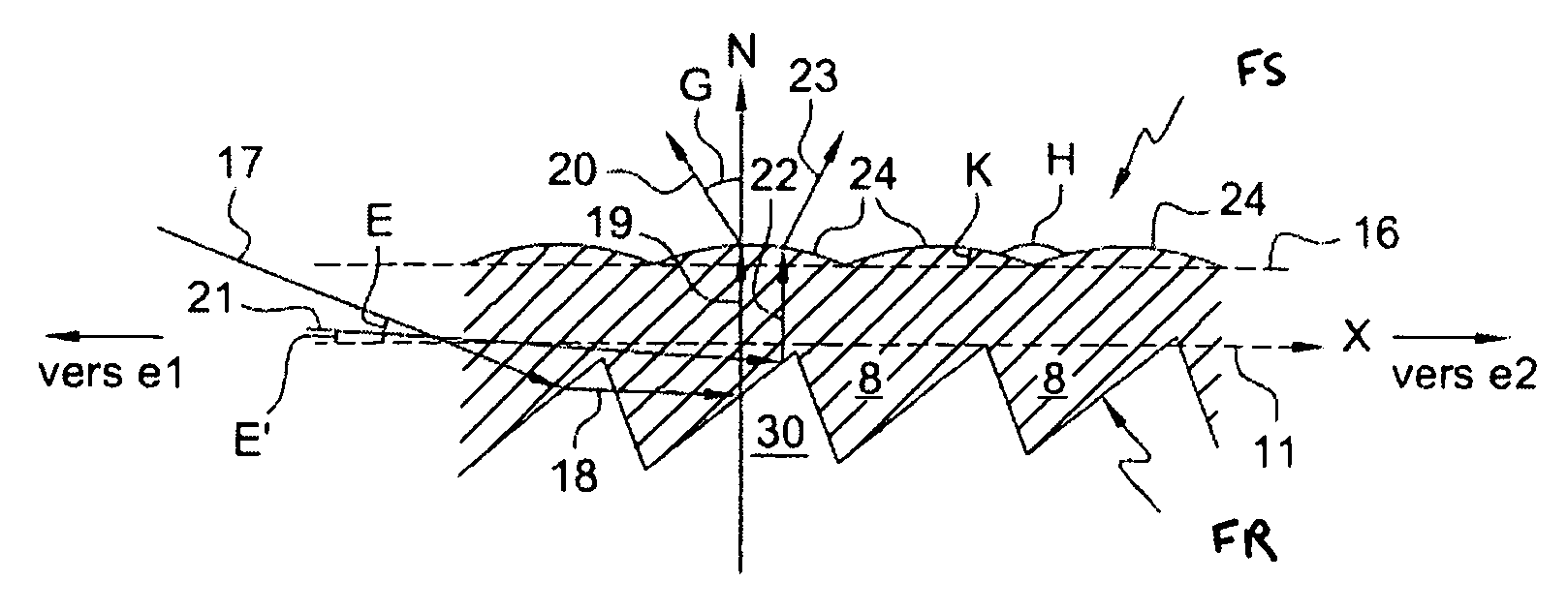
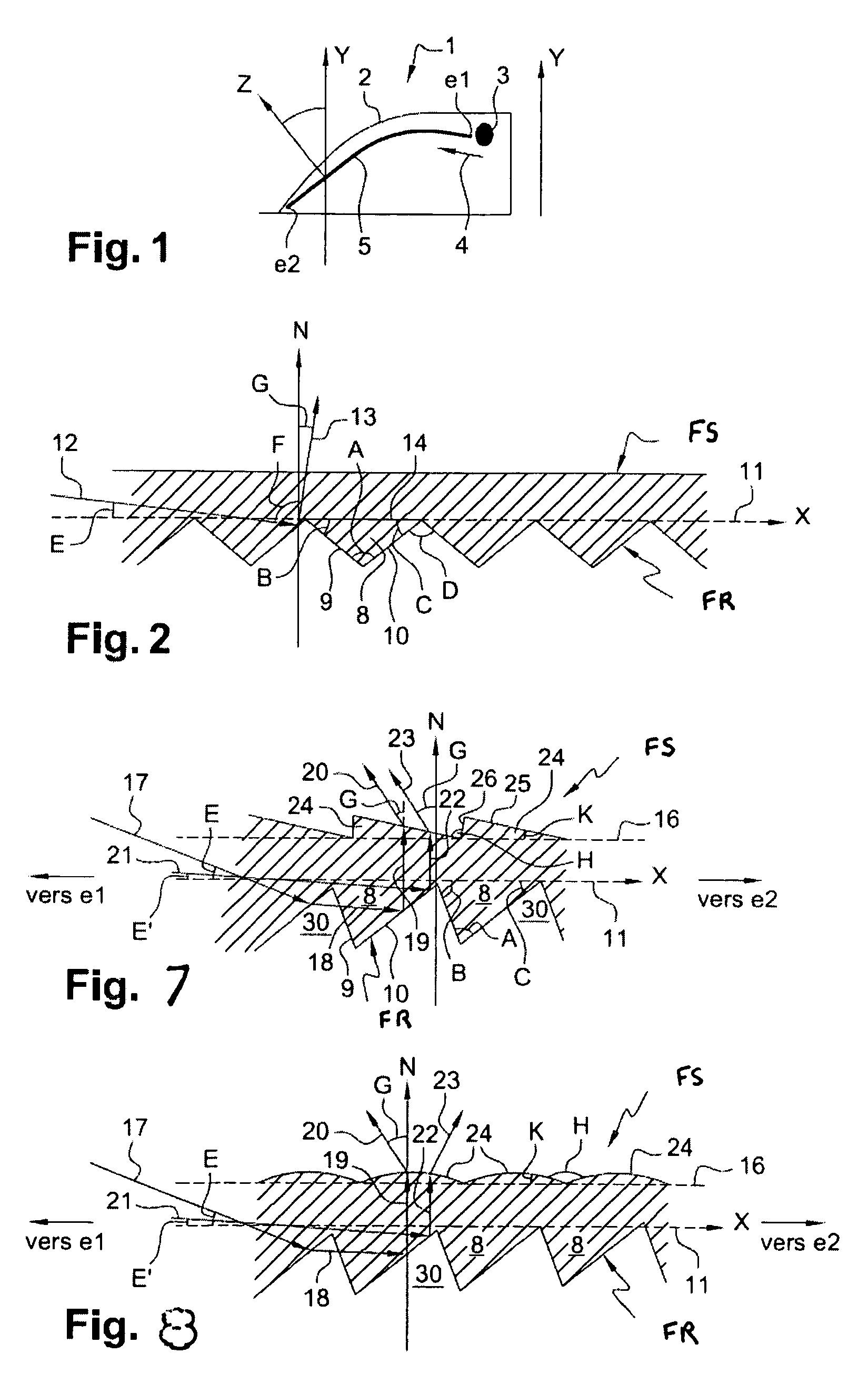
[0079]FIG. 6 depicts a light guide, which is modified on both its output face and its reflection face in accordance with the invention: the output face 6 comprises flutes which make it possible to straighten the light rays at the output of the optical guide, that is to say to make them leave the optical guide with a negative angle with respect to the normal N to the axis X of the guide, as depicted in FIG. 8, and the reflection face comprises prisms such as those described with the help of FIG. 4 in particular. Combining the two implementations of the invention on the same light guide is highly advantageous.
[0080]The flutes of the output face FS can have various shapes, for example, be in the shape of prisms or domes or else a combination of prisms and domes, as seen above with FIGS. 7 and 8. They are situated opposite active areas of the prisms 8 of the reflection face.
[0081]The prisms of the reflection face can be those described in FIG. 3, 4 or 5. The presence of flat surfaces 1...
PUM
 Abstract
Description
Claims
Application Information