Methods for controlling scene, camera and viewing parameters for altering perception of 3D imagery

a technology of scene and viewing parameters, applied in the field of stereography methods, tools and equipment, can solve the problems of time-consuming and produce results of less than consistent quality

Active Publication Date: 2013-04-11
WARNER BROS ENTERTAINMENT INC
View PDF7 Cites 11 Cited by
  • Summary
  • Abstract
  • Description
  • Claims
  • Application Information

AI Technical Summary

Benefits of technology

[0009]A more complete understanding of the methods, tools, and apparatuses for stereography disclosed herein will be afforded to those skilled in the art, as well as a realization of additional advantages and objects thereof, by consideration of the following detailed description. Reference will be made to the appended sheets of drawings which will first be described briefly.

Problems solved by technology

In other words, an art form that fails to apply precise rules governing how 3D content is acquired, transformed, and ultimately perceived by a viewer to obtain predictable and repeatable results, relying instead on trial and error and subjective adjustments, which may be both time consuming and produce results of less than consistent quality.

Method used


Image

  • Methods for controlling scene, camera and viewing parameters for altering perception of 3D imagery
  • Methods for controlling scene, camera and viewing parameters for altering perception of 3D imagery
  • Methods for controlling scene, camera and viewing parameters for altering perception of 3D imagery

Examples


example-1

Camera Parameters Using Method-1, Method-2, Method-3 and Method-4

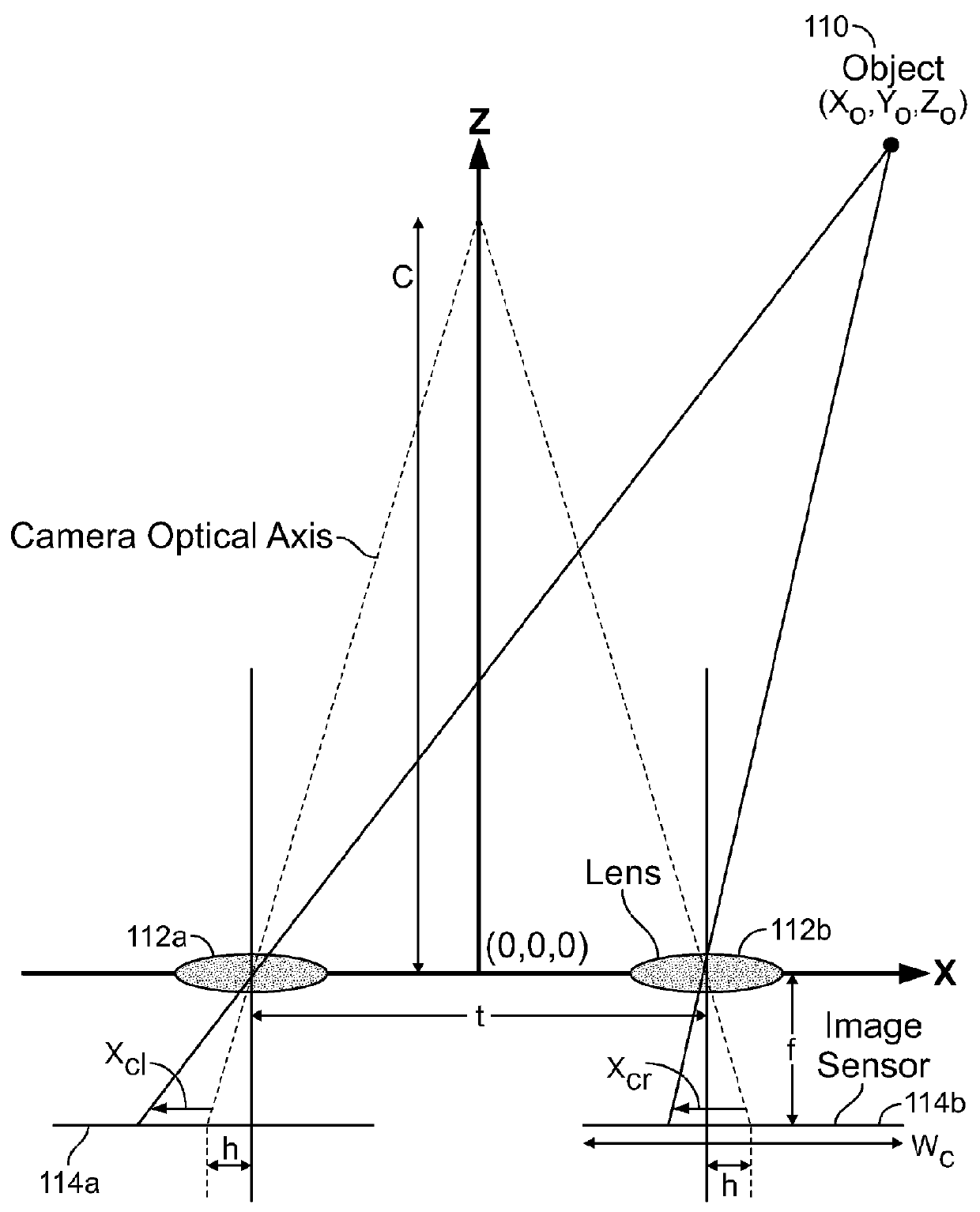
[0184]For this Example-1 (to be shown in the theatrical viewing environment), the film is being shot with a camera that uses a 4-Perf 2.39:1 film format sensor, which exposes an area on the film negative (or equivalently sized CCD or CMOS sensor) that has a width equal to 22 millimeters. Due to the 2:1 anamorphic lens used with the 4-perf 2.39:1 format, the physical sensor width Wc used in the formula's disclosed herein must be multiplied by two, giving the 4-Perf 2.39:1 sensor an effective width of Wc=44.0 mm. The focal length of the camera lens is f=75 mm. Therefore the camera's field of view is approximately equal to 2*arctan((Wc / 2) / f)=33 degrees.

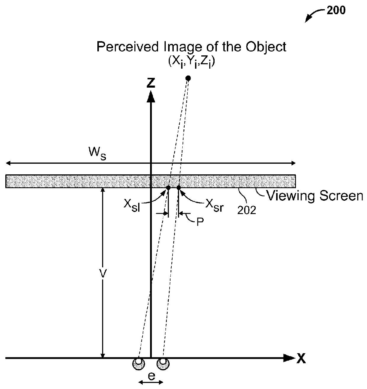
[0185]The image is projected on a screen that is 30 feet wide, e.g. the screen width Ws=30 feet=9144 mm. In this example, the magnification factor M has a value of M=Ws / Wc=9144 mm / 44.0 mm=207.82. The viewer is sitting 3 screen heights from the 2.39:1 aspect ratio screen, wh...

example-2

Camera parameters using Method-1, Method-2, Method-3 and Method-4

[0196]For Example-2, the same scene is used as in Example-1. However, a different film format and viewing environment is used (home entertainment viewing environment).

[0197]For Example-2, the film is being shot with a camera that uses a 5-Perf 65 mm film format sensor (also known as 5 / 70), which exposes an area on the film negative (or equivalently sized CCD or CMOS sensor) that has a width equal to 52.48 millimeters, so Wc=52.48 mm. As in Example-1, a 75 mm lens is used. This indicates that the camera's field of view is approximately 39 degrees.

[0198]In this example, the viewing environment is a 65-inch diagonal 3DTV, having an aspect ratio of 16:9. Therefore, the screen width Ws=1439 mm. The magnification factor can be computed as M=Ws / Wc=1439 mm / 52.48 mm=27.42. Here, the viewer is approximately 6 feet from the television and therefore has a viewing distance of V=1829 mm. This indicates that the viewer's field of vie...


PUM


Abstract

Mathematical relationships between the scene geometry, camera parameters, and viewing environment are used to control stereography to obtain various results influencing the viewer's perception of 3D imagery. The methods may include setting a horizontal shift, convergence distance, and camera interaxial parameter to achieve various effects. The methods may be implemented in a computer-implemented tool for interactively modifying scene parameters during a 2D-to-3D conversion process, which may then trigger the re-rendering of the 3D content on the fly.

Description

CROSS-REFERENCE TO RELATED APPLICATIONS[0001]This application claims priority, pursuant to 35 U.S.C. §119(e), to U.S. Provisional Application Ser. Nos. 61 / 491,157, filed May 28, 2011, and 61 / 533,777 filed Sep. 18, 2011. Each of the aforementioned applications is specifically incorporated herein by reference in its entirety.BACKGROUND OF THE INVENTION[0002]1. Field[0003]The present disclosure relates generally to methods, tools, and apparatus for stereography.[0004]2. Background[0005]Stereoscopic three-dimensional entertainment content (“3D content”) creation and distribution has dramatically increased in recent years. Various technical and creative methods are employed to produce 3D content, which from a viewer's subjective point of view may be enjoyable. To produce 3D content that meets the creative intent of the film maker, however, stereographers utilize a varied mix of creative and technical methods. In many instances, stereographers apply their methods in an iterative, subjecti...

Claims


Application Information

Patent Timeline
Patent Type & Authority Applications(United States)
IPC IPC(8): H04N13/00
CPCH04N13/0275H04N13/0055H04N13/275H04N13/204H04N13/128H04N13/189
Inventor COLLAR, BRADLEY T.SMITH, MICHAEL D.NOLAN, CHRISTOPHER E.
Owner WARNER BROS ENTERTAINMENT INC
Why Eureka
Try Eureka