
Electric shock proof lamp

Active Publication Date: 2013-04-11
ADVANCED CONNECTEK INC
View PDF2 Cites 1 Cited by
  • Summary
  • Abstract
  • Description
  • Claims
  • Application Information

AI Technical Summary

Benefits of technology

This patent aims to provide a light lamp that can prevent electric shock during installation. The light lamp has a rotating mechanism that connects or disconnects the electrodes from the light tube depending on the position of the mechanism. To install the light lamp, a worker first installs it in a receptacle and then rotates the light tube to connect the electrodes to the first holder, thus forming a circuit for powering the light lamp. This design prevents electric shock while installing the light lamp.

Problems solved by technology

Due to its technical defects, the LED is employed as an indicator light in an electronic device.
Although the LED is more costly than the traditional light emitting devices, the LED has a longer life span than the traditional light while being used in an environment equipped with good ventilation system.
Because the electric power is still electrically connected to the LED lamp, a user working on the LED installation may touch the disconnected electrodes and suffers an electric shock.

Method used


Image

  • Electric shock proof lamp
  • Electric shock proof lamp
  • Electric shock proof lamp

Examples


Embodiment Construction

[0019]Other features and advantages of the invention will become apparent in the following detailed description of a preferred embodiment with reference to the accompanying drawings.

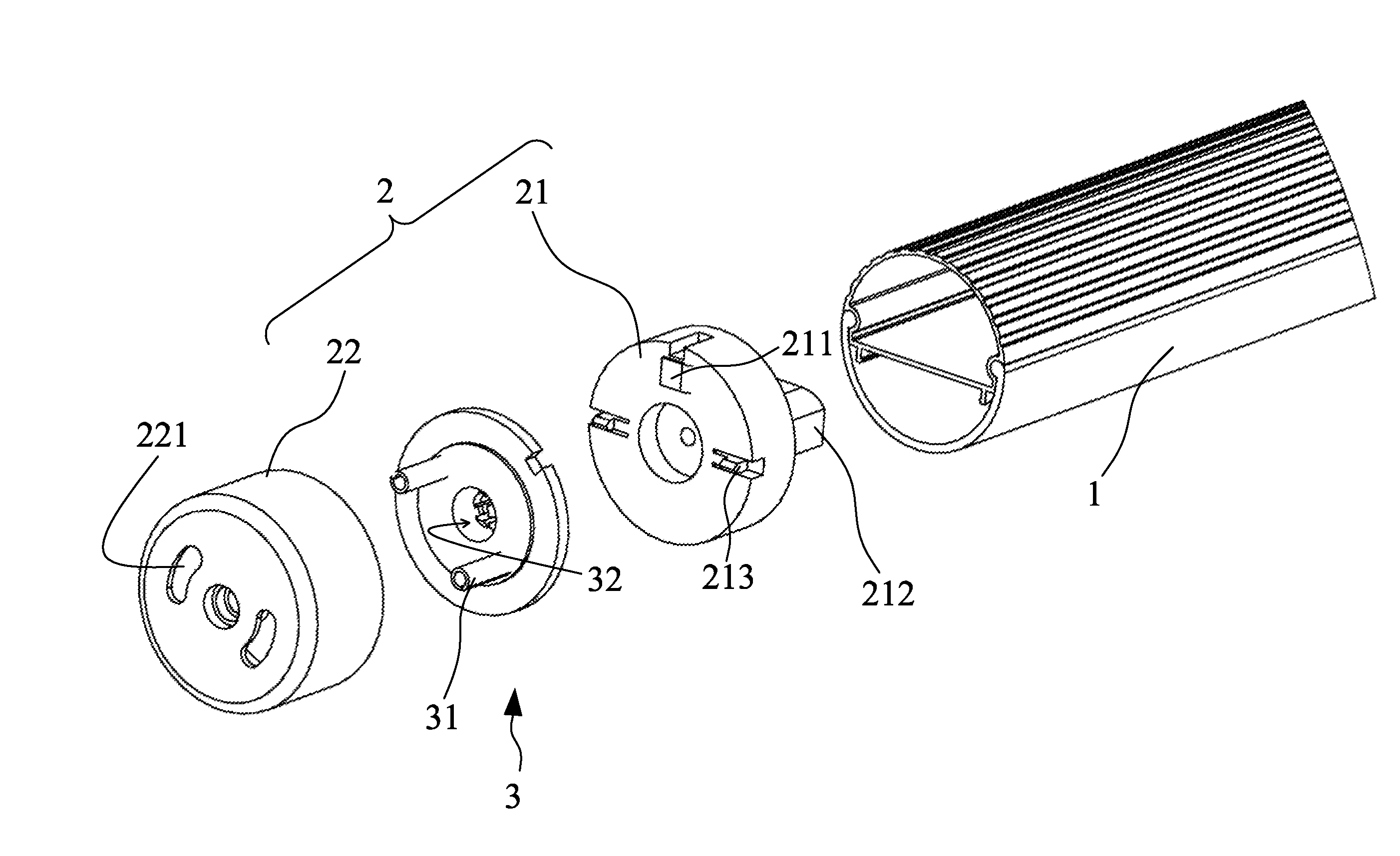
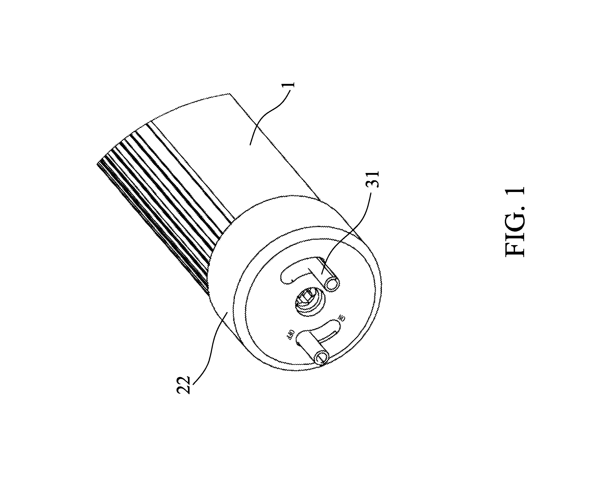
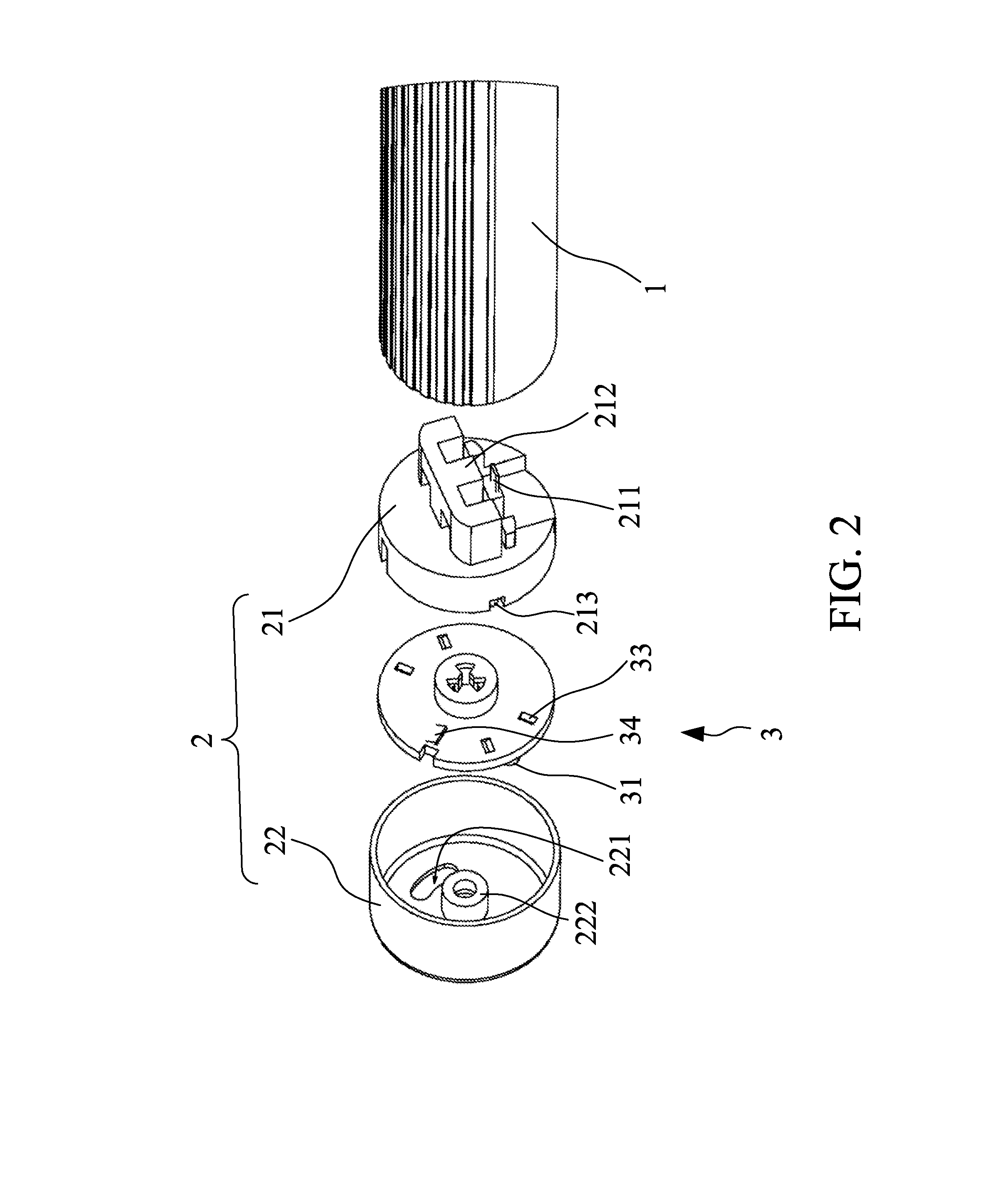
[0020]As shown in FIGS. 1 to 3, a preferred embodiment of a light lamp of the invention comprises a light tube (1), a first holder (2), and a first rotator (3).

[0021]The light tube (1) is an LED tube, and the LED tube has an LED positioned inside the LED tube via a way known in the art. For the requirement of lightness, the light tube (1) may have a proper number of LEDs positioned inside the light tube (1). The LED may be positioned in a desired angle inside the light tube (1) for better lighting performance.

[0022]The first holder (2) is mounted on a side of the light tube (1), and comprises a mounting space therein. The first holder (2) is a cylindrical casing, and includes a base (21) and a housing (22).

[0023]The base (21) is mounted on one side of the light tube (1) and comprises a first conductive c...


PUM


Abstract

A light lamp includes a light tube, a first holder and a first rotator. The first holder is mounted on a side of the light tube, and comprises a mounting space therein and two through holes in communication with the mounting space. The first rotator is movably received in the mounting space of the first holder between a first position and a second position, and comprises two electrodes extending from the through holes such that when the first rotator is in the first position, the electrodes are electrically connected to the light tube and when the first rotator is in the second position, the electrodes are electrically disconnected to the light tube.

Description

FIELD OF THE INVENTION[0001]The invention relates to a lamp, more particularly, to an electric shock proof lamp while being installed.BACKGROUND OF THE INVENTION[0002]A light-emitting diode (hereinafter “LED”) is a semiconductor, which emits light while being electrically connected to an electric power. Due to its technical defects, the LED is employed as an indicator light in an electronic device. Recently, as an LED emitting white light, the LED is adapted for much broader and varied uses, especially for interior lighting.[0003]When compared with a traditional light, an LED has the following advantages:[0004]1. High energy converting efficiency in low light intensity environment. Because the LED has this advantage, the LED is widely used in low intensity back light environment, such as the back light of a mobile phone, or the back light of a television.[0005]2. Rigid structure for better shock withstanding capability. As the LED is solid, the LED has a more rigid structure than a ...

Claims


Application Information

Patent Timeline
IPC IPC(8): F21V21/002
CPCH01R33/089F21V25/04F21K9/175F21Y2101/02F21K9/17F21K9/272F21Y2115/10F21V17/10F21V25/00
Inventor CHENG-WEI, CHENCHENG-JUNG, TSAIHAO-JAN, FUCHIN-TSAI, LIUWEN-HSIANG, CHIEN
Owner ADVANCED CONNECTEK INC
Learn More