Method for operating a drive train

a drive train and drive technology, applied in mechanical equipment, external condition input parameters, transportation and packaging, etc., can solve the problems of unfavorable drive train operation and higher fuel consumption of internal combustion engines, and achieve the effect of reducing the requirement of fuel or fuel consumption

Inactive Publication Date: 2013-04-11
ZF FRIEDRICHSHAFEN AG
View PDF2 Cites 0 Cited by
  • Summary
  • Abstract
  • Description
  • Claims
  • Application Information

AI Technical Summary

Benefits of technology

[0011]The method according to the invention allows a mode of operation of a drive train with an auxiliary output on the engine side which is advantageous from the standpoint of energy. In particular, the fuel requirement or fuel consumption can be reduced.

Problems solved by technology

From the standpoint of energy such operation of the drive train is not favorable.
In particular, it can lead to higher fuel consumption by the internal combustion engine.

Method used


Image

  • Method for operating a drive train
  • Method for operating a drive train
  • Method for operating a drive train

Examples


Embodiment Construction

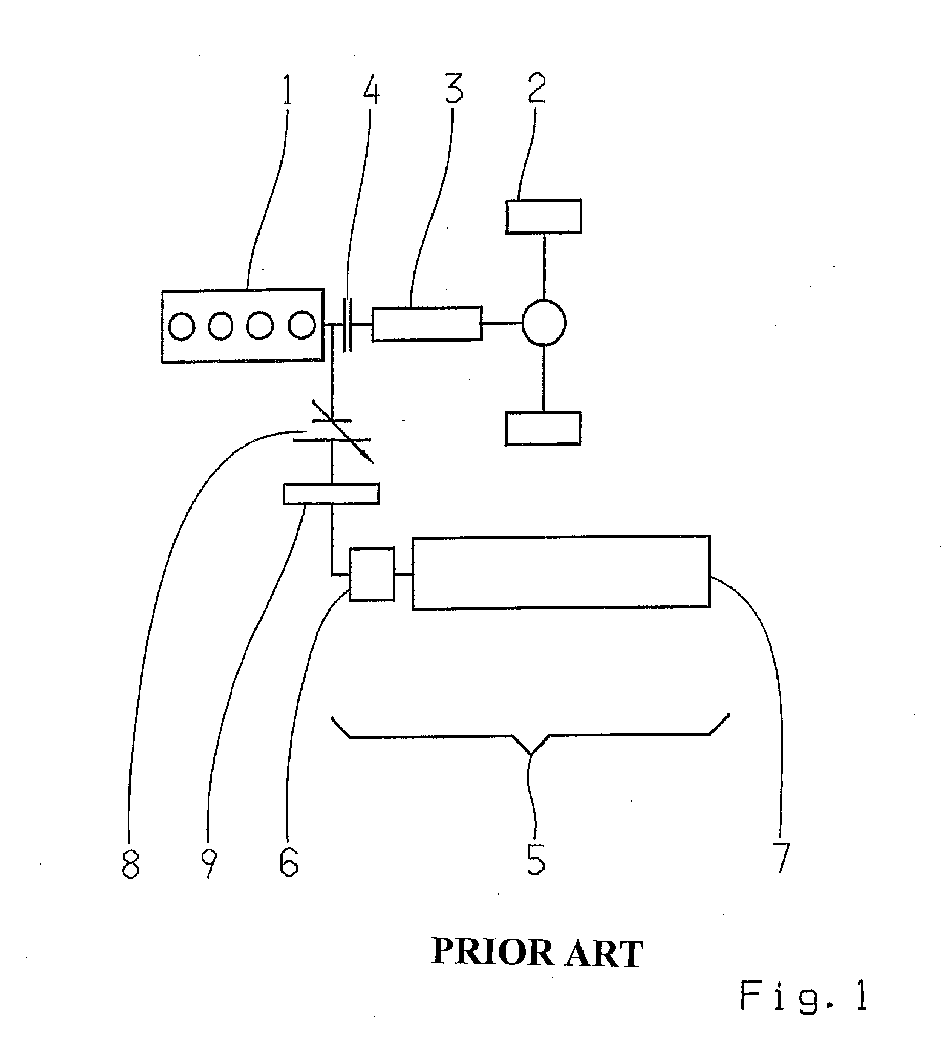
[0016]The present invention concerns a method for operating a drive train of a motor vehicle having an auxiliary output on the engine side, in particular the drive train shown in FIG. 1.

[0017]Although the invention is described below with reference to this preferred embodiment of a drive train, already at this point it should be mentioned that the method according to the invention can also be used with other drive train configurations having an auxiliary output on the engine side.

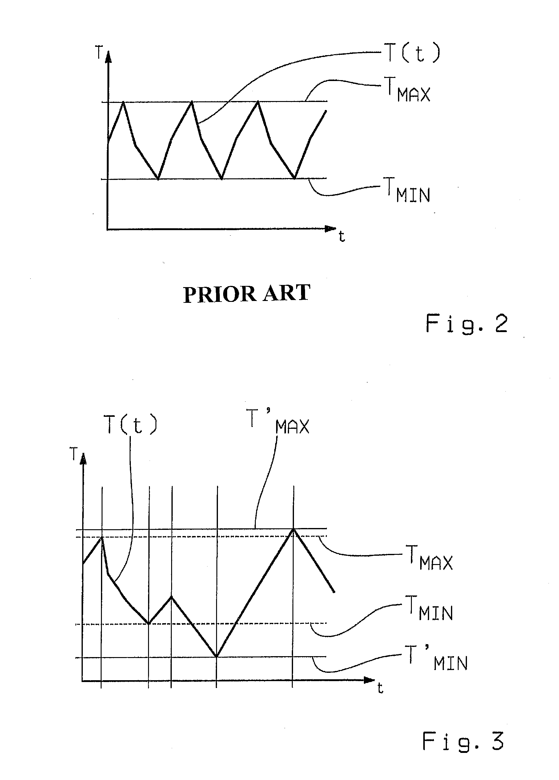
[0018]The use of the invention is not limited to drive trains whose auxiliary output is in the form of a cooling aggregate and a refrigerating trailer; rather, drive trains with other auxiliary outputs that comprise a storage function in regard to their condition parameter to be regulated can also be operated using the method according to the invention, for example drive trains whose auxiliary outputs are hydraulic auxiliary outputs.

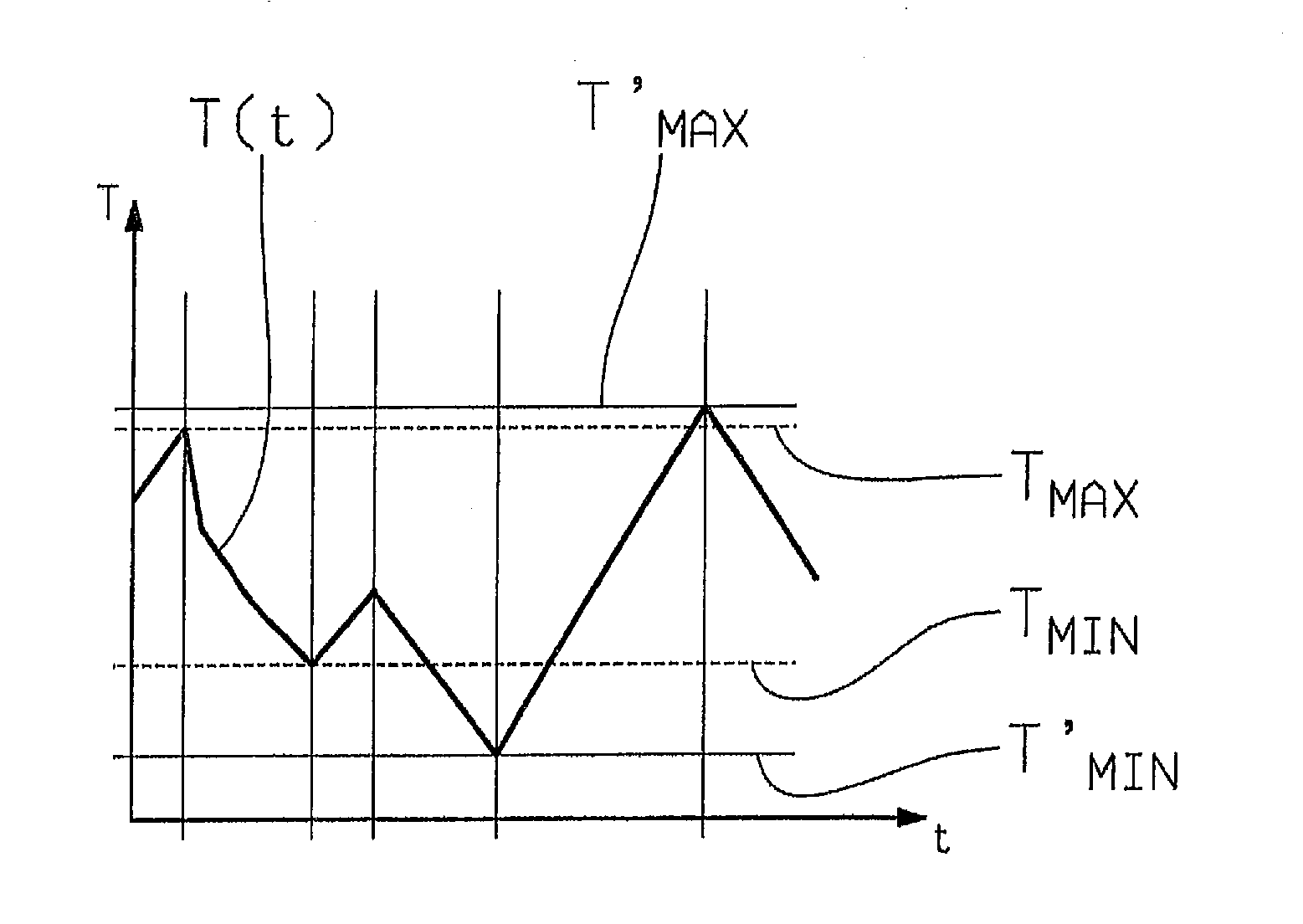
[0019]In the context of the present invention, the procedure for regulating...


PUM


Abstract

A method of operating a drive-train comprising an auxiliary output on the engine side that can be coupled to the combustion engine via a continuously variable transmission and a generator such that when the engine is running, the generator can be driven at a constant rotational speed regardless of the speed of the engine, such that a condition parameter of the auxiliary output is regulated between a pair of limit values. The condition parameter is regulated as a function of its current actual value, the limit values of the condition parameter and also as a function of a current and/or anticipated driving situation such that parameters are determined, in the regulator, for the energy input into the auxiliary output as a function of these input data, and hence for a corresponding energy uptake from the engine.

Description

[0001]This application is a National Stage completion of PCT / EP2011 / 057167 filed May 5, 2011, which claims priority from German patent application serial no. 10 2010 030 247.3 filed Jun. 17, 2010.FIELD OF THE INVENTION[0002]The invention concerns a method for operating a drive train of a motor vehicle.BACKGROUND OF THE INVENTION[0003]FIG. 1 shows the basic structure of a drive train of a motor vehicle known from the prior art, which has an auxiliary output on the engine side. Thus, the drive train in FIG. 1 comprises a drive aggregate consisting of an internal combustion engine 1, with a transmission 3 connected between the internal combustion engine 1 and a drive output 2. The transmission 3 converts rotational speeds and torques and thereby transmits traction force provided by the internal combustion engine 1 to the drive output 2. In the drive train of FIG. 1, a clutch 4 is connected between the internal combustion engine 1 and the transmission 3, by means of which the internal c...

Claims


Application Information

Patent Timeline
Patent Type & Authority Applications(United States)
IPC IPC(8): B60W10/101B60W30/18B60W30/188
CPCB60W10/06B60W10/30B60W30/18127B60W30/1882B60W30/1886B60W50/0097Y10T477/613Y02T10/56Y02T10/84B60W10/101Y10T477/23Y10T477/6223B60W2550/402B60W2556/50Y02T10/40
Inventor BANERJEE, ALEXANDERHUNOLD, BERNARD
Owner ZF FRIEDRICHSHAFEN AG
Why Eureka
Try Eureka