Wire harness clip and method of mounting wire harness clip onto vehicle

a technology of wire harness clip and vehicle, which is applied in the direction of machine supports, manufacturing tools, other domestic objects, etc., can solve the problem of difficult change of mounting position

Inactive Publication Date: 2013-04-18
SUMITOMO WIRING SYST LTD
View PDF5 Cites 12 Cited by
  • Summary
  • Abstract
  • Description
  • Claims
  • Application Information

AI Technical Summary

Benefits of technology

The wire harness clip of this patent allows for easy adjustment and secure mounting of a wire harness to a bracket in a vehicle. The clip has a C-type metal clip that can retreat within a C-type resin clip, making it easy to hold the clip on the bracket and make final adjustments. The clip can then be fully anchored to the bracket by pressing down on the tabs and lifting the press-down tabs with a bracket. This design simplifies the installation process and ensures a reliable mounting of the wire harness.

Problems solved by technology

The technical problem addressed in this patent text is related to improving the efficiency and accuracy of infrared temperature measurement for non-contact type thermometers, particularly for small measurement targets.

Method used


Image

  • Wire harness clip and method of mounting wire harness clip onto vehicle
  • Wire harness clip and method of mounting wire harness clip onto vehicle
  • Wire harness clip and method of mounting wire harness clip onto vehicle

Examples


Embodiment Construction

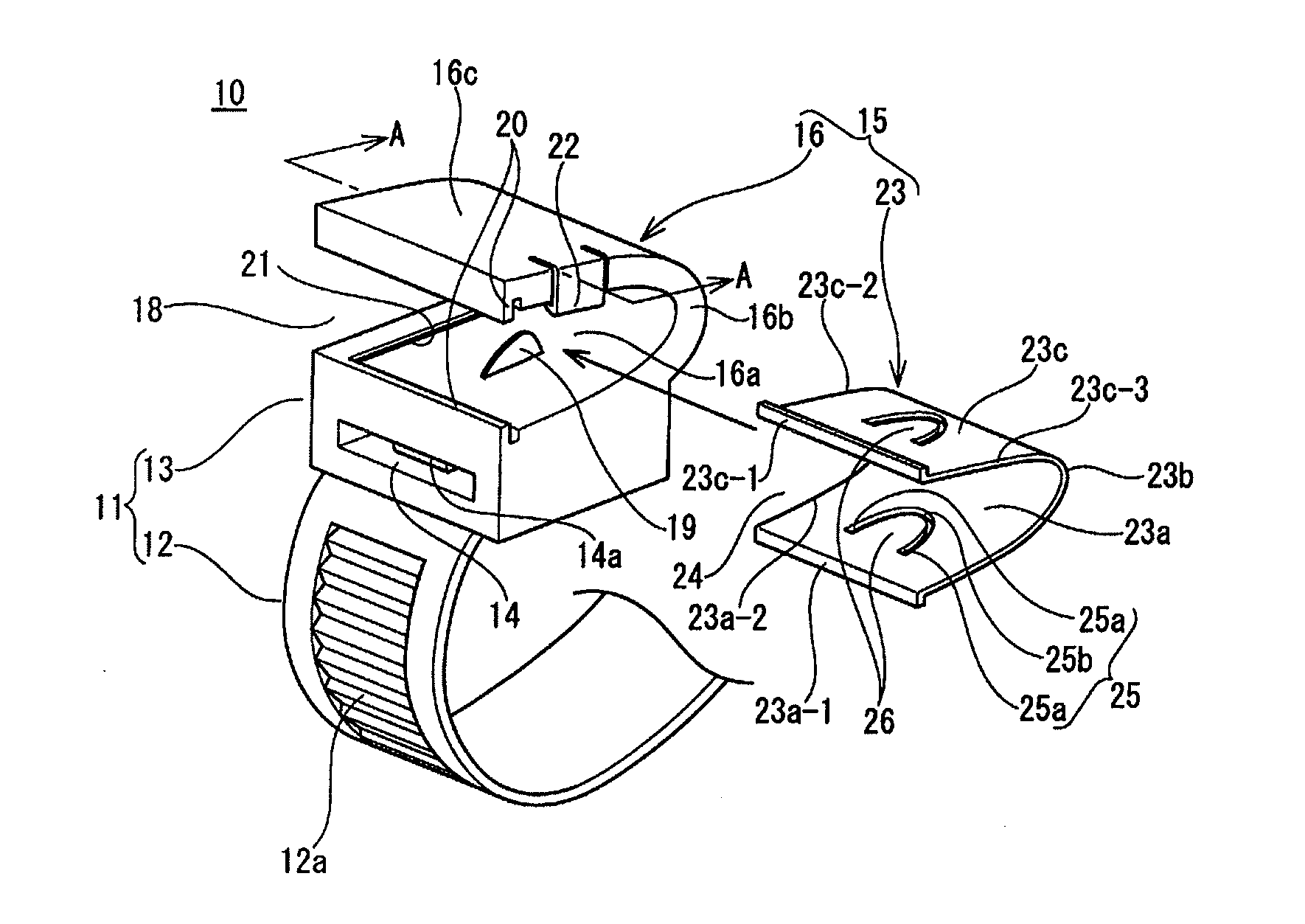
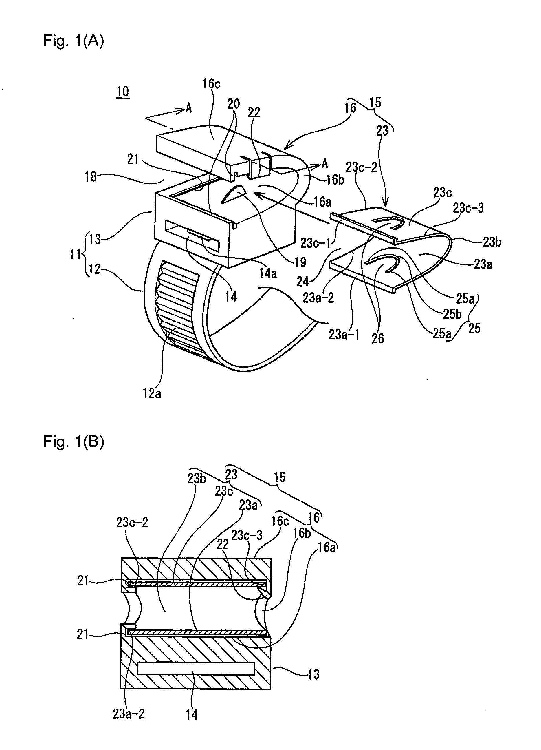
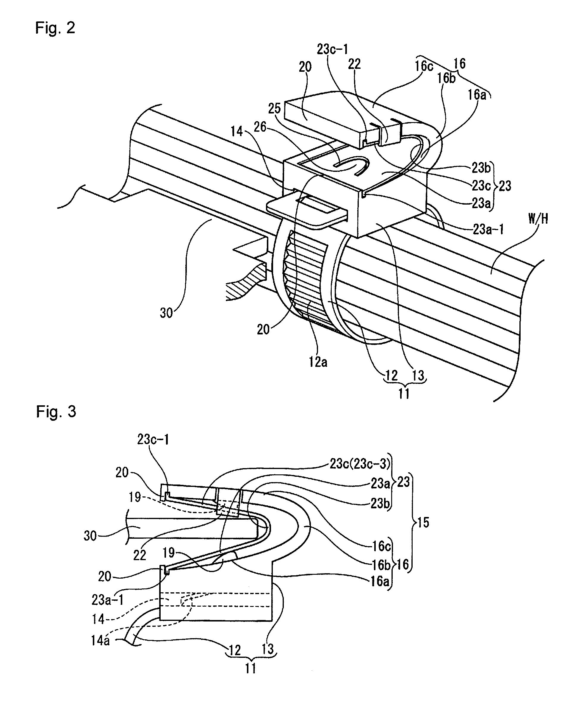
[0024]Hereafter, an embodiment of a wire harness clip in the present invention is described with reference to the drawings. FIGS. 1 to 4 illustrate the present embodiment. As shown in FIG. 2, a wire harness clip 10 according to the present embodiment is configured from a band-type wire harness mount 11 and a clip 15, the band-type wire harness mount 11 anchored by winding around an outer circumference of a wire harness W / H, and the clip 15 mounted to a flat plate-shaped bracket 30 made of metal or resin on a vehicle body side. The band-type wire harness mount 11 is configured from a band 12 which wraps around the outer circumference of the wire harness W / H and a band tightener 13 which tightens and anchors the band 12. The band 12 projects from a position near a lower edge on a first lateral surface of the band tightener 13. The band tightener 13 includes a band latching hole 14 through which the band 12 wrapped around the wire harness W / H is passed from a second lateral surface of ...


PUM


Abstract

The present invention includes a C-type resin clip projecting from an exterior surface on a band tightener in a band-type wire harness mount or from a front surface on a middle portion of a substrate in a substrate-type wire harness mount, and a C-type metal clip having a length shorter than the C-type resin clip. The C-type metal clip is mounted between upper and lower tabs of the C-type resin clip. A pressing projection is provided on opposing interior surfaces of each of the upper and lower tabs of the C-type resin clip, and a press-down tab is provided on the upper and lower tabs of the C-type metal clip. When a bracket is pressed in between the upper and lower tabs of the C-type metal clip, the press-down tabs are lifted by the pressing projections and both the upper and lower surfaces of the bracket are pinched and held.

Description


Claims


Application Information

Patent Timeline
Owner SUMITOMO WIRING SYST LTD
Why Eureka
Try Eureka