Substrate type antenna

a substrate type, antenna technology, applied in the direction of individual energised antenna arrays, resonant antennas, separate antenna unit combinations, etc., can solve the problems of increasing the complexity of configuration, and achieve the effect of simple configuration, high gain enhancement, and high band enhancemen

Active Publication Date: 2014-06-03
NISSEI LTD +1
View PDF6 Cites 13 Cited by
  • Summary
  • Abstract
  • Description
  • Claims
  • Application Information

AI Technical Summary

Benefits of technology

[0006]An object of the present invention is to provide a substrate type antenna configured to be capable of realizing high gain enhancement and high band enhancement in a simple configuration.
[0008]With this configuration, a plurality of antennas can simply be configured on a thin substrate while sharing feeding points of a second joint pattern formed in the other substrate surface, thereby making it possible to realize broadbanding at high gain, which cannot be obtained in the case of a single antenna.
[0009]In addition to the above configuration, the present invention includes another substrate disposed on the second joint pattern side of the substrate integrally therewith; a loop-like fourth joint pattern, one spot of which being divided, which is formed at a position corresponding to the second joint pattern, of a substrate surface on the side opposite to the second joint pattern at another substrate referred to above; and other antennas connected to both end terminals of the fourth joint pattern at a position where the fourth joint pattern is divided. This thus results in new addition of one antenna. Therefore, gain can be combined using three antennas in total, and high gain enhancement and broadbanding can further be achieved. Moreover, the tree antennas can be configured while sharing feeding points formed in the other substrate surface of the substrate, thus making it possible to simplify the entire configuration.
[0010]Further, in addition to the above configuration, the present invention includes another substrate disposed on the second joint pattern side of the substrate integrally therewith; a loop-like fourth joint pattern, one spot of which being divided, which is formed at a position corresponding to the second joint pattern, of a substrate surface on the side opposite to a surface on the side of formation of the second joint pattern at another substrate referred to above; a loop-like fifth joint pattern, one spot of which being divided, which is formed substantially concentrically with the fourth joint pattern and at the position corresponding to the second joint pattern; and other antennas respectively different from one another, which are respectively connected to both end terminals of the fourth and fifth joint patterns at the positions where the fourth joint pattern and the fifth joint pattern are divided. This thus results in new addition of two antennas. High gain enhancement and broadbanding can therefore be achieved. Further, the four antennas can be configured while sharing feeding points formed in the other substrate surface of the substrate, thus making it possible to simplify the entire configuration.
[0011]According to the substrate type antenna of the present invention, a plurality of antennas can simply be configured on a thin substrate while sharing feeding points of a second joint pattern formed in the other substrate surface, thus making it possible to realize broadbanding at high gain, which cannot be obtained in the case of a single antenna.

Problems solved by technology

In the conventional substrate type antenna, however, its configuration increases in complexity if one attempts to achieve a further gain improvement by a combination of a plurality of antennas.

Method used


Image

  • Substrate type antenna
  • Substrate type antenna
  • Substrate type antenna

Examples


Embodiment Construction

[0026]Preferred embodiments of the present invention will be explained hereinafter based on the accompanying drawings.

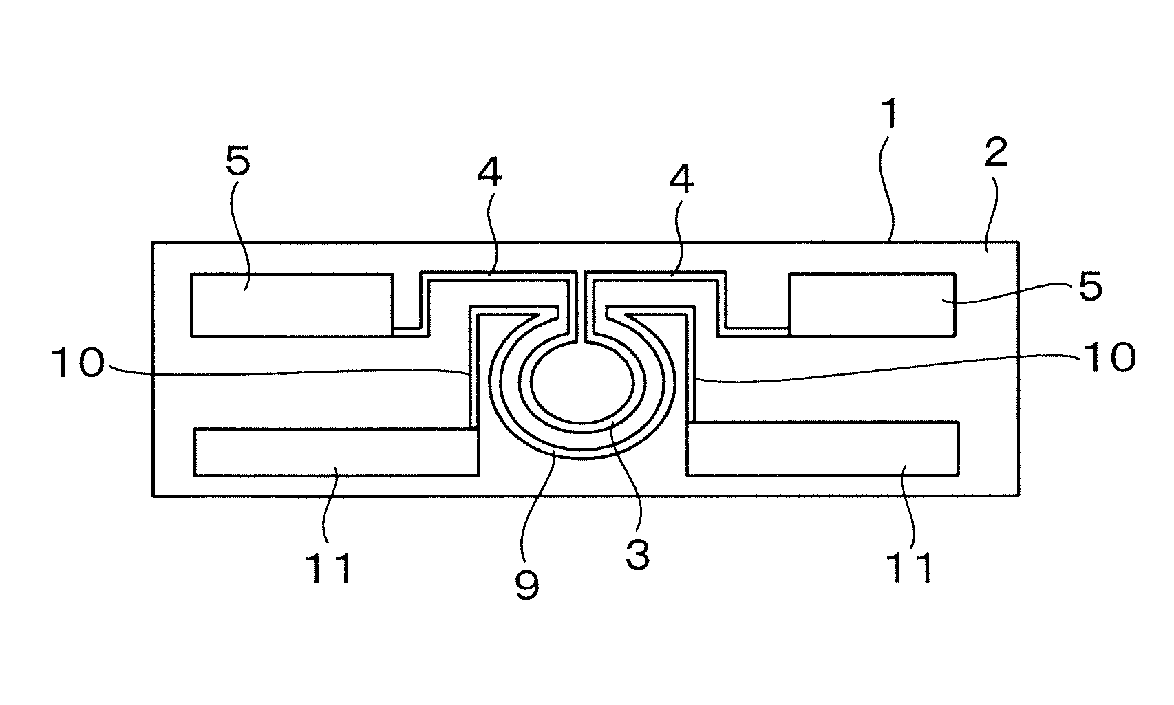
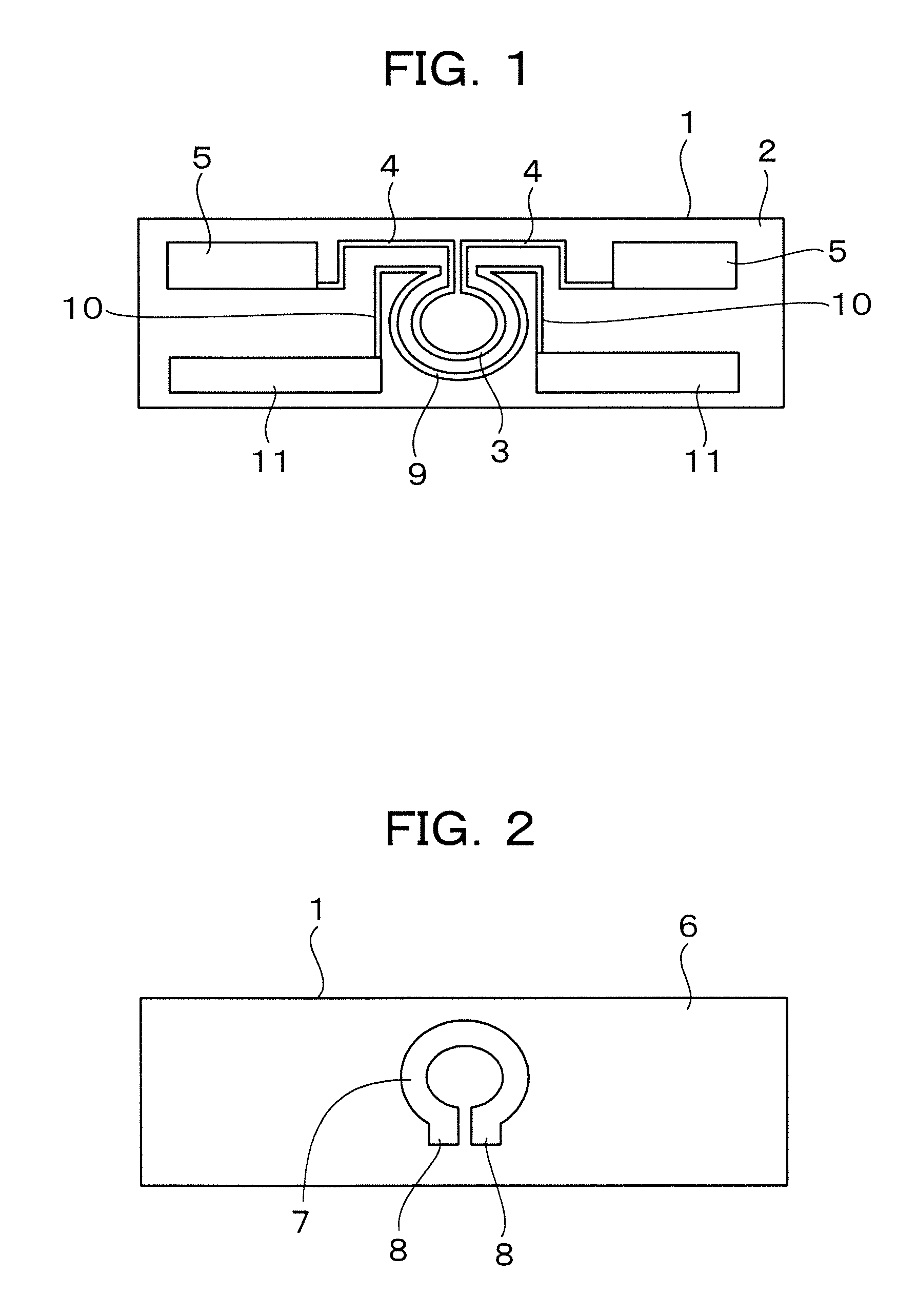
[0027]FIGS. 1 and 2 are respectively plan views showing upper and lower surfaces of a substrate type antenna according to one embodiment of the present invention.

[0028]A loop-like first coupling-part or joint pattern 3, one spot of which is divided as shown in FIG. 1, is formed in an upper surface 2 corresponding to one substrate surface of a substrate 1 comprised of a dielectric material. Dipole antennas 5 are respectively connected to both end terminals of the first joint pattern 3 at a position where the first joint pattern 3 is divided, through electric paths 4. A loop-like second joint pattern 7, one spot of which being divided, is formed in a lower surface 6 corresponding to the other substrate surface of the substrate 1 shown in FIG. 2. Feeding points 8 are formed at their corresponding divided ends of the second joint pattern 7.

[0029]A loop-like third joint p...


PUM


Abstract

The present invention provides a substrate type antenna capable of realizing high gain enhancement and high band enhancement in a simple configuration. In the substrate type antenna, a loop-like first joint pattern whose one spot is divided, is formed in one substrate surface of a substrate made of a dielectric material. Antennas are respectively connected to both end terminals of the first joint pattern at a position where the first joint pattern is divided. A loop-like second joint pattern formed at a position corresponding to the first joint pattern and whose one spot is divided, is formed in the other substrate surface of the substrate. A loop-like third joint pattern which is substantially concentric with the first joint pattern and which is formed at a position corresponding to the second joint pattern and whose spot is divided, is formed in the one substrate surface of the substrate. Other antennas are respectively connected to both end terminals of the third joint pattern at a position where the third joint pattern is divided.

Description

BACKGROUND OF THE INVENTION[0001]1. Field of the Invention[0002]The present invention relates to a substrate type antenna configured on a thin substrate.[0003]2. Description of the Related Art[0004]As a conventional substrate type antenna of this type, there has been known a configuration which has a substrate made of a dielectric material, a loop-like first coupled-portion or joint pattern formed at a first substrate surface of the substrate and divided at one spot thereof, and a loop-like second joint pattern formed at a second substrate surface of the substrate and divided at one spot, and in which electrostatic capacitively-coupled and magnetic inductively-coupled states are formed between the first joint pattern and the second joint pattern (refer to, for example, a patent document 1 (Japanese Patent Application Laid-Open No. 2007-142666)). According to such a configuration, unlike a conventional case in which patterns are formed on the same plane, the electrostatic capacitivel...

Claims


Application Information

Patent Timeline
Patent Type & Authority Patents(United States)
IPC IPC(8): H01Q21/00H01Q5/10
CPCH01Q9/285H01Q21/30H01Q5/0072H01Q9/24H01Q5/40
Inventor KANEKO, TUTOMUKARAKAMA, TAKAHISA
Owner NISSEI LTD
Why Eureka
Try Eureka