Laser-marking film
a laser marking and film technology, applied in the field of laser marking film, can solve the problems of difficult formation of a layer of laser marking that exhibits homogeneous laser absorption, heat is not sufficiently generated, and images for representing data are not vividly formed, so as to improve the vividness of laser marking, improve the accuracy of laser marking, and improve the effect of laser marking
- Summary
- Abstract
- Description
- Claims
- Application Information
AI Technical Summary
Benefits of technology
Problems solved by technology
Method used
Image
Examples
experimental examples
[0063]The present invention is described by the following experiments. Described below are evaluation of markings, laser beam irradiation conditions employed for the laser marking and the reddish brown iron oxide used in the experiments described below.
Evaluation
[0064]Vividness of the ink for laser marking after irradiated with the laser beam was confirmed with the eye. The evaluation was on the following basis.
[0065]⊚: Very vivid.
[0066]◯: Vivid.
[0067]Δ: Not so vivid.
[0068]×: Not vivid.
[0069]Apparatus for laser beam irradiation:[0070]Three-dimensional YVO4 laser marker manufactured by Keyence Co.
[0071]Laser beam wavelength: 1064 nm
[0072]Laser beam output range: 35% to 50% at 50 watts
[0073]Reddish brown iron oxide (α-Fe2O3), particle diameter: 1 to 2 μm
experimental example 1
[0074]An ink for laser marking was prepared by using an urethane resin as a resin binder, a reddish brown iron oxide comprising red ion oxide as an inorganic pigment, a titanium oxide as a white inorganic pigment and a toluene.MEK (methyl ethyl ketone).IPA (isopropyl alcohol) as an organic solvent. The reddish brown iron oxide was used in an amount of 3 parts by weight and the titanium oxide was used in an amount of 810 parts by weight per 100 parts by weight of the resin binder (i.e., the weight ratio of reddish brown iron oxide:titanium oxide was 1:270).
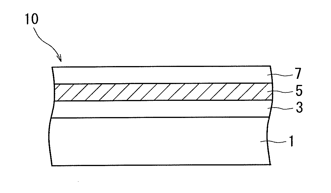
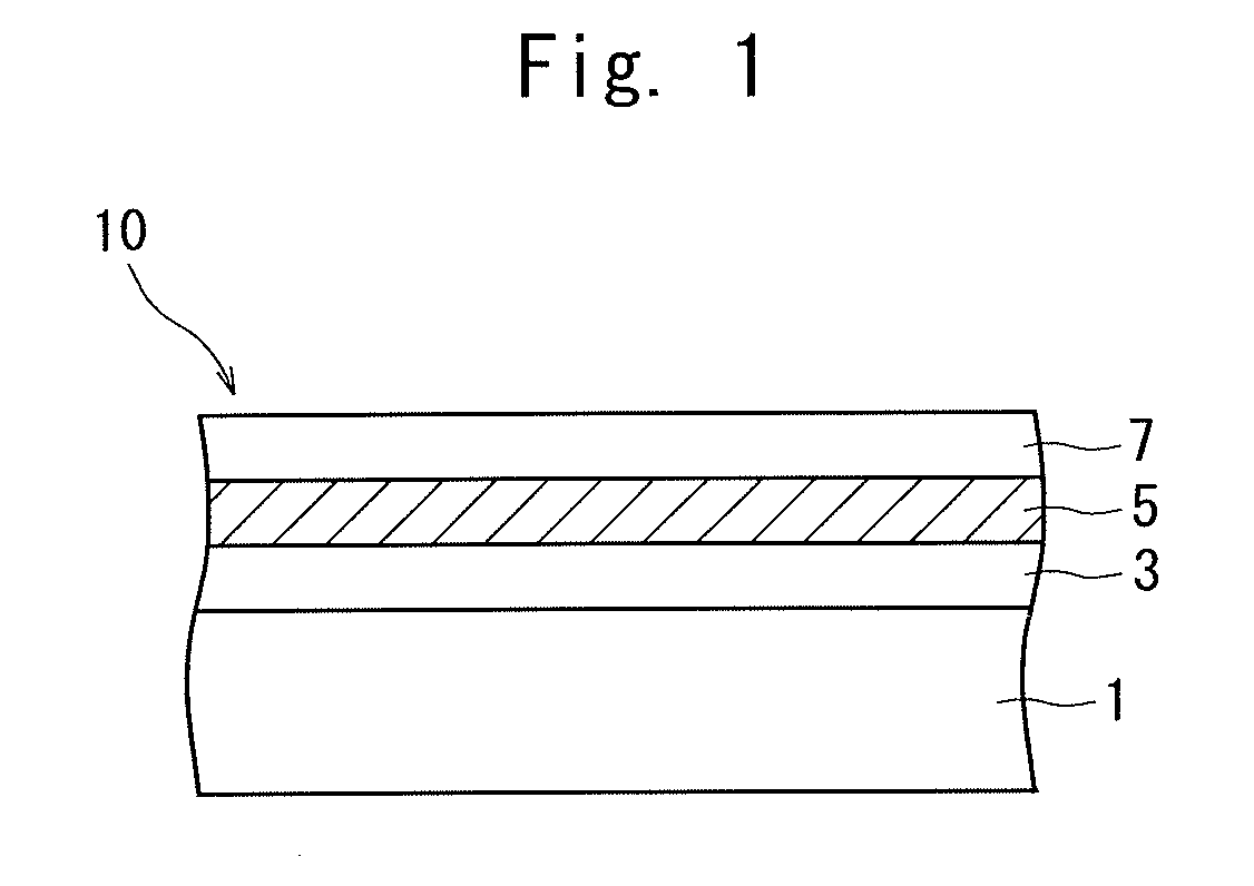
[0075]Next, the ink for laser marking was printed on a 12 μm-thick protection layer of polyethylene terephthalate and was dried to form an ink layer and on which was formed a 3 μm-thick underlying layer of urethane resin containing titanium oxide that was a white inorganic pigment. Thereafter, a 70 μm-thick base film of polypropylene was stuck thereto via an adhesive, and the thus obtained film was irradiated with a laser beam from...
experimental example 2
[0077]A film was prepared in the same manner as in Experimental Example 1 but without adding the titanium oxide that was the white inorganic pigment to the ink for laser marking and without forming the underlying layer. The film was irradiated with the laser beam and was evaluated in the same manner as in Experimental Example 1.
PUM
| Property | Measurement | Unit |
|---|---|---|
| Percent by mass | aaaaa | aaaaa |
| Weight | aaaaa | aaaaa |
| Weight ratio | aaaaa | aaaaa |
Abstract
Description
Claims
Application Information
 - R&D
- Intellectual Property
- Life Sciences
- Materials
- Tech Scout
- Unparalleled Data Quality
- Higher Quality Content
- 60% Fewer Hallucinations
Browse by: Latest US Patents, China's latest patents, Technical Efficacy Thesaurus, Application Domain, Technology Topic, Popular Technical Reports.
© 2025 PatSnap. All rights reserved.Legal|Privacy policy|Modern Slavery Act Transparency Statement|Sitemap|About US| Contact US: help@patsnap.com


