Method and system for high-throughput and low-power communication links in a distributed transceiver network

a communication link and distributed transceiver technology, applied in the field of signal processing for communication systems, can solve the problem that the higher frequency may experience high propagation loss

Active Publication Date: 2013-04-18
GOLBA LLC
View PDF6 Cites 71 Cited by
  • Summary
  • Abstract
  • Description
  • Claims
  • Application Information

AI Technical Summary

Problems solved by technology

However, these higher frequencies may experience high propagation loss.

Method used


Image

  • Method and system for high-throughput and low-power communication links in a distributed transceiver network
  • Method and system for high-throughput and low-power communication links in a distributed transceiver network
  • Method and system for high-throughput and low-power communication links in a distributed transceiver network

Examples


Embodiment Construction

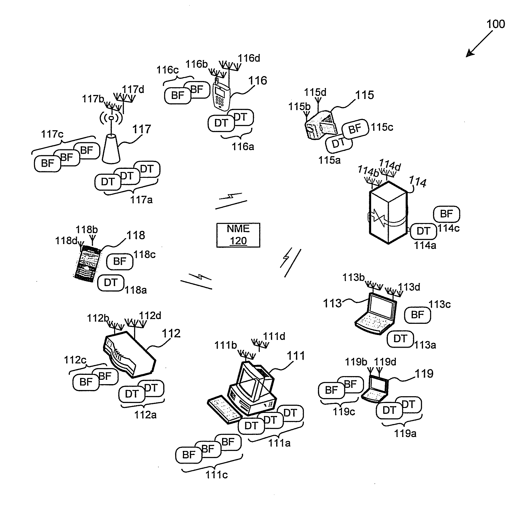
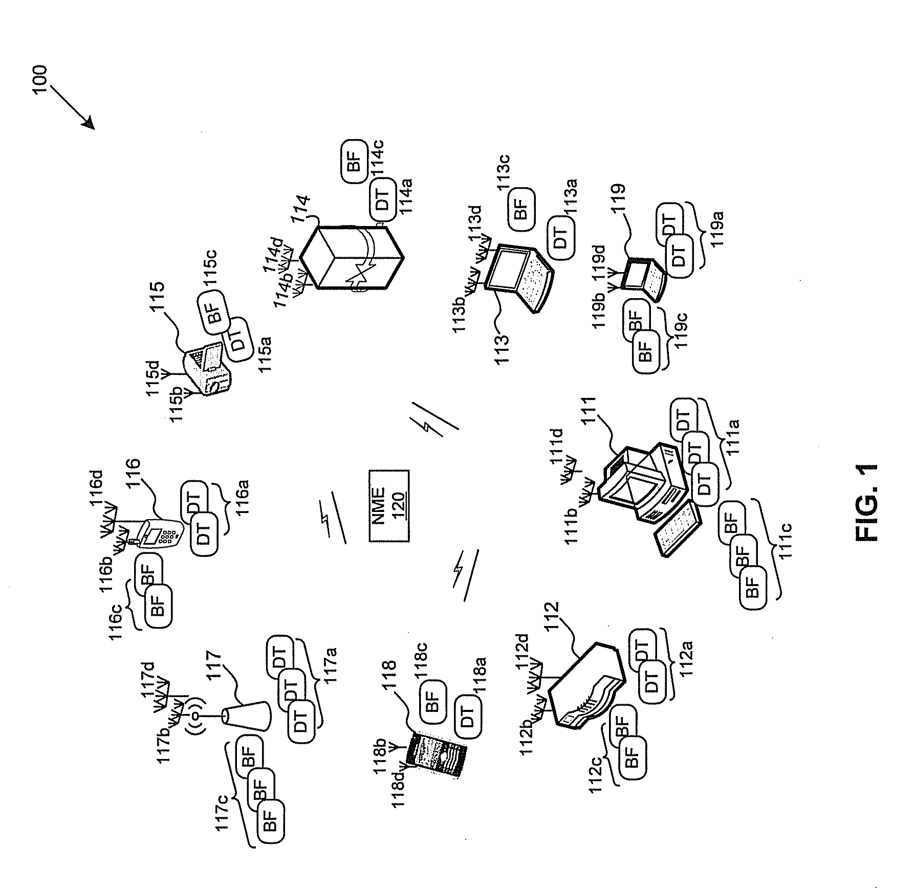
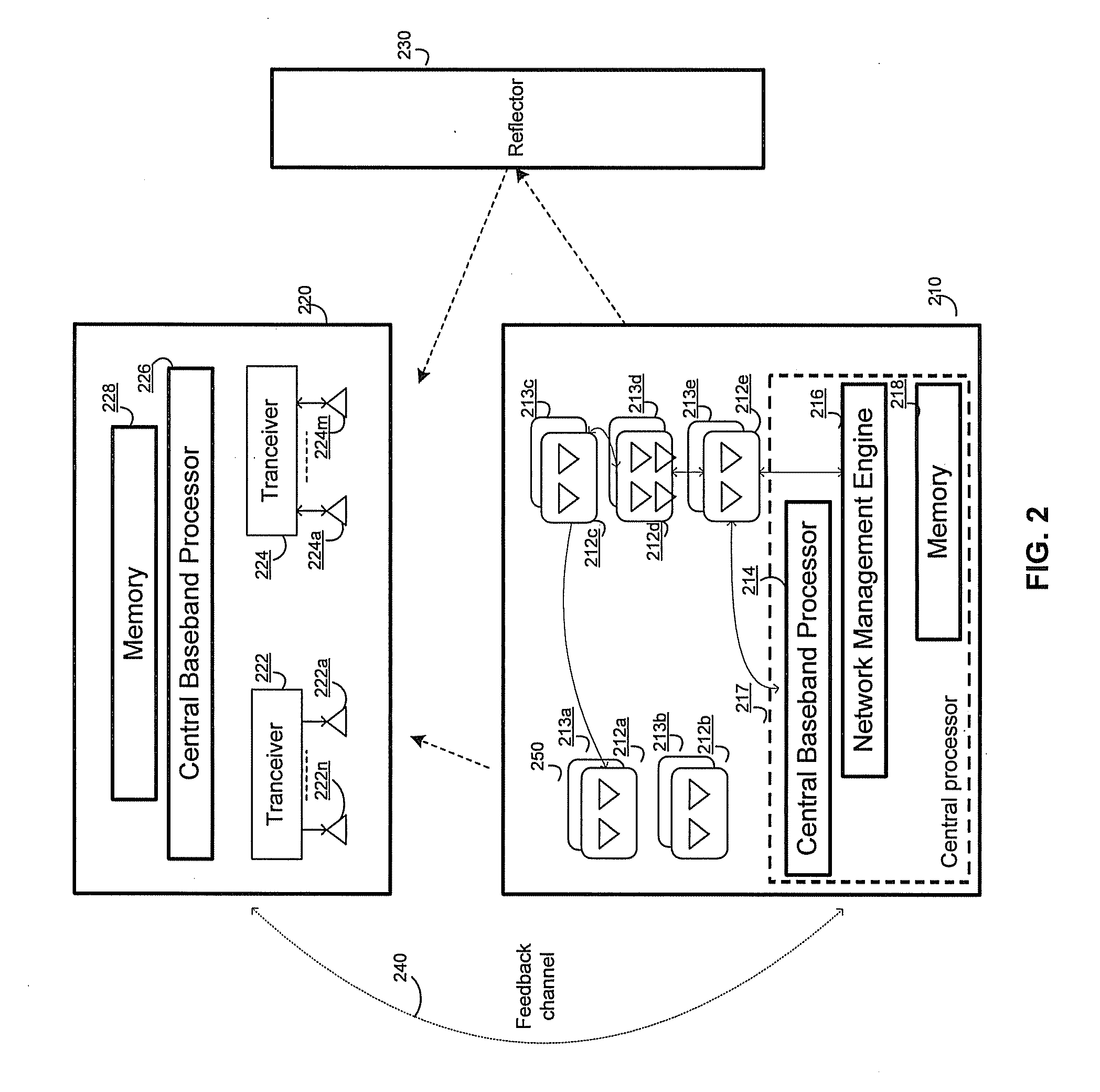
[0028]Certain embodiments of the invention may be found in a method and system for high-throughput and low-power communication links in a distributed transceiver network. In accordance with various exemplary embodiments of the invention, a device comprises a plurality of distributed transceivers, a plurality of distributed beamformers, a baseband processor, and a network management engine. The plurality of distributed transceivers may be operable to perform beamforming in a radio frequency band, and the plurality of distributed beamformers may perform beamforming in an intermediate frequency band. Each of the distributed transceivers is coupled to a corresponding one of the distributed beamformers. Each transceiver-beamformer pair may be connected to the baseband processor within the device utilizing the same communication medium such as cable. For transmission, the baseband processor may generate a data stream at baseband. Up-converters within the device may convert the data stream...


PUM


Abstract

A device comprises a plurality of distributed transceivers, a plurality of distributed beamformers, a baseband processor, and a network management engine. The distributed transceivers perform beamforming in a radio frequency band. The distributed beamformers, however, performs beamforming in an intermediate frequency band. Each of the distributed transceivers is coupled to a corresponding one of the distributed beamformers. Each transceiver-beamformer pair is coupled to the baseband processor utilizing a same communication medium such as a cable. For transmission, a data stream generated at baseband is converted to intermediate frequencies. With a low-power transmission, the distributed beamformers transmit the data stream wirelessly in the intermediate frequencies to a receiving device. With a normal-power transmission, the distributed transceivers transmit the data stream to the receiving device in the radio frequency band. The transceivers and the beamformers are turned OFF whenever not being used. A high-throughput communication link may be established through resource sharing.

Description

CROSS-REFERENCE TO RELATED APPLICATIONS / INCORPORATION BY REFERENCE[0001]This patent application makes reference to, claims priority to and claims benefit from U.S. Provisional Patent Application Ser. No. 61 / 548,201 filed on Oct. 17, 2011.[0002]This application makes reference to:[0003]U.S. application Ser. No. ______ (Attorney Docket No. 25066US02) filed on May 16, 2012;[0004]U.S. application Ser. No. ______ (Attorney Docket No. 25067US02) filed on May 16, 2012;[0005]U.S. application Ser. No. ______ (Attorney Docket No. 25068US02) filed on May 16, 2012;[0006]U.S. application Ser. No. ______ (Attorney Docket No. 25069US02) filed on May 16, 2012;[0007]U.S. application Ser. No. ______ (Attorney Docket No. 25070US02) filed on May 16, 2012; and[0008]U.S. application Ser. No. ______ (Attorney Docket No. 25071 US02) filed on May 16, 2012.[0009]Each of the above stated applications is hereby incorporated herein by reference in its entirety.FIELD OF THE INVENTION[0010]Certain embodiments of ...

Claims


Application Information

Patent Timeline
Patent Type & Authority Applications(United States)
IPC IPC(8): H04B7/02H04W4/80
CPCH04W88/06H04W88/02H04B7/0689H04W84/12H04L5/0032H04W4/008Y02B60/50H04W4/80H04B1/401Y02D30/70H04W72/51H04W72/54H04B7/0408H04B7/043H04B1/40H04L27/12H04W72/542H04B7/0413H04B7/0897H04W24/08H04W72/0453H04W72/046H04W72/0473H04B7/024
Inventor MOSHFEGHI, MEHRAN
Owner GOLBA LLC
Why Eureka
Try Eureka